|
Fault Models
A fault model is an engineering model of something that could go wrong in the construction or operation of a piece of equipment. From the model, the designer or user can then predict the consequences of this particular fault. Fault models can be used in almost all branches of engineering. Basic fault models Basic fault models in digital circuits include: *Static faults, which give incorrect values at any speed and sensitized by performing only one operation: ** The stuck-at fault model. A signal, or gate output, is stuck at a 0 or 1 value, independent of the inputs to the circuit. ** The bridging fault model. Two signals are connected together when they should not be. Depending on the logic circuitry employed, this may result in a ''wired-OR'' or ''wired-AND'' logic function. Since there are ''O(n^2)'' potential bridging faults, they are normally restricted to signals that are physically adjacent in the design. ** The transistor faults. This model is used to describe faults ... [...More Info...] [...Related Items...] OR: [Wikipedia] [Google] [Baidu] |
Digital Circuit
In theoretical computer science, a circuit is a model of computation in which input values proceed through a sequence of gates, each of which computes a function. Circuits of this kind provide a generalization of Boolean circuits and a mathematical model for digital logic circuits. Circuits are defined by the gates they contain and the values the gates can produce. For example, the values in a Boolean circuit are Boolean values, and the circuit includes conjunction, disjunction, and negation gates. The values in an integer circuit are sets of integers and the gates compute set union, set intersection, and set complement, as well as the arithmetic operations addition and multiplication. Formal definition A circuit is a triplet (M, L, G), where * M is a set of values, * L is a set of gate labels, each of which is a function from M^ to M for some non-negative integer i (where i represents the number of inputs to the gate), and * G is a labelled graph, labelled directed acyclic gra ... [...More Info...] [...Related Items...] OR: [Wikipedia] [Google] [Baidu] |
Stuck-at Fault
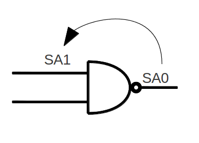
A stuck-at fault is a particular fault model used by fault simulators and automatic test pattern generation (ATPG) tools to mimic a manufacturing defect within an integrated circuit. Individual signals and pins are assumed to be ''stuck'' at Logical '1', '0' and 'X'. For example, an input is tied to a logical 1 state during test generation to assure that a manufacturing defect with that type of behavior can be found with a specific test pattern. Likewise the input could be tied to a logical 0 to model the behavior of a defective circuit that cannot switch its output pin. Not all faults can be analyzed using the stuck-at fault model. Compensation for static hazards, namely branching signals, can render a circuit untestable using this model. Also, redundant circuits cannot be tested using this model, since by design there is no change in any output as a result of a single fault. Single stuck at line Single stuck line is a fault model used in digital circuits. It is used for post ... [...More Info...] [...Related Items...] OR: [Wikipedia] [Google] [Baidu] |
Bridging Fault
In electronic engineering, a bridging fault consists of two signals that are connected when they should not be. Depending on the logic circuitry employed, this may result in a wired-OR or wired-AND logic function. Since there are O(n^2) potential bridging faults, they are normally restricted to signals that are physically adjacent in the design. Modeling bridge fault Bridging to VDD or Vss is equivalent to stuck at fault model. Traditionally bridged signals were modeled with logic AND or OR of signals. If one driver dominates the other driver in a bridging situation, the dominant driver forces the logic to the other one, in such case a ''dominant bridging fault'' is used. To better reflect the reality of CMOS VLSI devices, a ''dominant AND or dominant OR bridging fault model'' is used where dominant driver keeps its value, while the other signal value is the result of AND (or OR) of its own value with the dominant driver. References"Bridging Fault Model"from ''Test and Diagnosis fo ... [...More Info...] [...Related Items...] OR: [Wikipedia] [Google] [Baidu] |
Transistor Fault
Transistor Fault model is a Fault model used to describe faults for CMOS logic gates. At transistor level, a transistor may be stuck-short or stuck-open. In stuck-short, a transistor behaves as it is always conducts (or stuck-on), and stuck-open is when a transistor never conducts current (or stuck-off). Stuck-short will usually produce a short between VDD and VSS.  In the example picture, a faulty PMOS logic, PMOS transistor in a CMOS NAND Gate is shown (M3-highlighted transistor). If M3 is stuck-open, then in case we apply A=1 and B=0 then the output of the circuit will become Z. And if M3 is stuck-short, then the output will always be connected to 1, and it also may short VCC to GND in case we apply A=B=1.
Digital electronics
Electronic design
Elect ...
[...More Info...] [...Related Items...] OR: [Wikipedia] [Google] [Baidu] |
