|
IC Layout
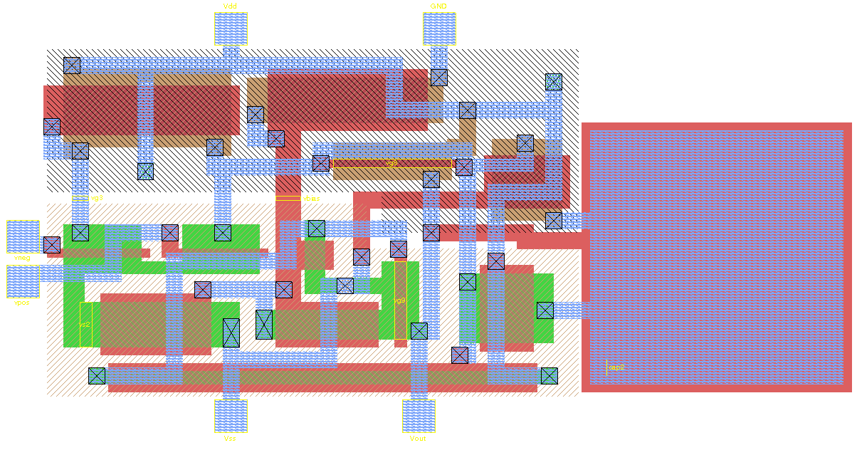
In integrated circuit design, integrated circuit (IC) layout, also known IC mask layout or mask design, is the representation of an integrated circuit in terms of planar geometric shapes which correspond to the patterns of metal, oxide, or semiconductor layers that make up the components of the integrated circuit. Originally the overall process was called tapeout, as historically early ICs used graphical black crepe tape on mylar media for photo imaging (erroneously believed to reference magnetic data—the photo process greatly predated magnetic media). When using a standard process—where the interaction of the many chemical, thermal, and photographic variables is known and carefully controlled—the behaviour of the final integrated circuit depends largely on the positions and interconnections of the geometric shapes. Using a computer-aided layout tool, the layout engineer—or layout technician—places and connects all of the components that make up the chip such that ... [...More Info...] [...Related Items...] OR: [Wikipedia] [Google] [Baidu] |
Mask Data Preparation
A mask is an object normally worn on the face, typically for protection, disguise, performance, or entertainment, and often employed for rituals and rites. Masks have been used since antiquity for both ceremonial and practical purposes, as well as in the performing arts and for entertainment. They are usually worn on the face, although they may also be positioned for effect elsewhere on the wearer's body. In art history, especially sculpture, "mask" is the term for a face without a body that is not modelled in the round (which would make it a "head"), but for example appears in low relief. Etymology The word "mask" appeared in English in the 1530s, from Middle French ''masque'' "covering to hide or guard the face", derived in turn from Italian ''maschera'', from Medieval Latin ''masca'' "mask, specter, nightmare". This word is of uncertain origin, perhaps from Arabic ''maskharah'' مَسْخَرَۃٌ "buffoon", from the verb ''sakhira'' "to ridicule". However, it may a ... [...More Info...] [...Related Items...] OR: [Wikipedia] [Google] [Baidu] |
Interconnects (integrated Circuits)
In integrated circuits (ICs), interconnects are structures that connect two or more circuit elements (such as transistors) together electrically. The design and layout of interconnects on an IC is vital to its proper function, performance, power efficiency, reliability, and fabrication yield. The material interconnects are made from depends on many factors. Chemical and mechanical compatibility with the semiconductor substrate and the dielectric between the levels of interconnect is necessary, otherwise barrier layers are needed. Suitability for fabrication is also required; some chemistries and processes prevent the integration of materials and unit processes into a larger technology (recipe) for IC fabrication. In fabrication, interconnects are formed during the back-end-of-line after the fabrication of the transistors on the substrate. Interconnects are classified as ''local'' or ''global'' interconnects depending on the signal propagation distance it is able to support. The wi ... [...More Info...] [...Related Items...] OR: [Wikipedia] [Google] [Baidu] |
Polygon
In geometry, a polygon () is a plane figure made up of line segments connected to form a closed polygonal chain. The segments of a closed polygonal chain are called its '' edges'' or ''sides''. The points where two edges meet are the polygon's '' vertices'' or ''corners''. An ''n''-gon is a polygon with ''n'' sides; for example, a triangle is a 3-gon. A simple polygon is one which does not intersect itself. More precisely, the only allowed intersections among the line segments that make up the polygon are the shared endpoints of consecutive segments in the polygonal chain. A simple polygon is the boundary of a region of the plane that is called a ''solid polygon''. The interior of a solid polygon is its ''body'', also known as a ''polygonal region'' or ''polygonal area''. In contexts where one is concerned only with simple and solid polygons, a ''polygon'' may refer only to a simple polygon or to a solid polygon. A polygonal chain may cross over itself, creating star polyg ... [...More Info...] [...Related Items...] OR: [Wikipedia] [Google] [Baidu] |
Standard Cell
In semiconductor design, standard-cell methodology is a method of designing application-specific integrated circuits (ASICs) with mostly digital-logic features. Standard-cell methodology is an example of design abstraction, whereby a low-level very-large-scale integration ( VLSI) layout is encapsulated into an abstract logic representation (such as a NAND gate). Cell-based methodology – the general class to which standard cells belong – makes it possible for one designer to focus on the high-level (logical function) aspect of digital design, while another designer focuses on the implementation (physical) aspect. Along with semiconductor manufacturing advances, standard-cell methodology has helped designers scale ASICs from comparatively simple single-function ICs (of several thousand gates), to complex multi-million gate system-on-a-chip (SoC) devices. Construction of a standard cell A standard cell is a group of transistor and interconnect structures that provides a bo ... [...More Info...] [...Related Items...] OR: [Wikipedia] [Google] [Baidu] |
Schematic-driven Layout
Schematic driven layout is the concept in integrated circuit layout or PCB PCB may refer to: Science and technology * Polychlorinated biphenyl, an organic chlorine compound, now recognized as an environmental toxin and classified as a persistent organic pollutant * Printed circuit board, a board used in electronics * P ... layout where the EDA software links the schematic and layout databases. It was one of the first big steps forward in layout software from the days when editing tools were simply handling drawn polygons. Features Schematic-driven layout allows for several features that make the layout designer's job easier and faster. One of the most important is that changes to the circuit schematic are easily translated to the layout. Another is that the connections between components in the schematic are graphically displayed in the layout ensuring work is correct by construction. References * Clein, Dan. (2000). ''CMOS IC Layout''. Newnes. {{ISBN, 0-7506-7194-7 El ... [...More Info...] [...Related Items...] OR: [Wikipedia] [Google] [Baidu] |
Place And Route
Place and route (also called PnR or P&R) is a stage in the design of printed circuit boards, integrated circuits, and field-programmable gate arrays. As implied by the name, it is composed of two steps, placement and routing. The first step, placement, involves deciding where to place all electronic components, circuitry, and logic elements in a generally limited amount of space. This is followed by routing, which decides the exact design of all the wires needed to connect the placed components. This step must implement all the desired connections while following the rules and limitations of the manufacturing process. Place and route is used in several contexts: * Printed circuit boards, during which components are graphically placed on the board and the wires drawn between them * Integrated circuits, during which a layout of a larger block of the circuit or the whole circuit is created from layouts of smaller sub-blocks * FPGAs, during which logic elements are placed and i ... [...More Info...] [...Related Items...] OR: [Wikipedia] [Google] [Baidu] |
Electronic Design Automation
Electronic design automation (EDA), also referred to as electronic computer-aided design (ECAD), is a category of software tools for designing Electronics, electronic systems such as integrated circuits and printed circuit boards. The tools work together in a Design flow (EDA), design flow that chip designers use to design and analyze entire semiconductor chips. Since a modern semiconductor chip can have billions of components, EDA tools are essential for their design; this article in particular describes EDA specifically with respect to integrated circuits (ICs). History Early days The earliest electronic design automation is attributed to IBM with the documentation of its IBM 700/7000 series, 700 series computers in the 1950s. Prior to the development of EDA, integrated circuits were designed by hand and manually laid out. Some advanced shops used geometric software to generate tapes for a Gerber format, Gerber photoplotter, responsible for generating a monochromatic ex ... [...More Info...] [...Related Items...] OR: [Wikipedia] [Google] [Baidu] |
IC Layout Editor
An integrated circuit layout editor or IC layout editor is an electronic design automation software tool that allows a user to digitize the shapes and patterns that form an integrated circuit. Typically the view will include the components (usually as pcells), metal routing tracks, vias and electrical pins. Software of this type is similar to computer aided drafting software, but is specialized for the task of integrated circuit layout. The typical flow for the layout of analog circuits might be : :1. The layout engineer receives the schematic from the designer in electrical form :2. Either the tool or the layout engineer creates a physical view of the circuit including all of the required components, wires, layers and pads. :3. The layout engineer positions the components to minimize both the area required and the negative effects of layout parasitics upon the circuit performance and also to allow efficient routing to components. :4. The layout engineer uses metal routing and ot ... [...More Info...] [...Related Items...] OR: [Wikipedia] [Google] [Baidu] |
Printed Circuit Board
A printed circuit board (PCB), also called printed wiring board (PWB), is a Lamination, laminated sandwich structure of electrical conduction, conductive and Insulator (electricity), insulating layers, each with a pattern of traces, planes and other features (similar to wires on a flat surface) Chemical milling, etched from one or more sheet layers of copper laminated onto or between sheet layers of a non-conductive substrate. PCBs are used to connect or Electrical wiring, "wire" Electronic component, components to one another in an electronic circuit. Electrical components may be fixed to conductive pads on the outer layers, generally by soldering, which both electrically connects and mechanically fastens the components to the board. Another manufacturing process adds Via (electronics), vias, metal-lined drilled holes that enable electrical interconnections between conductive layers, to boards with more than a single side. Printed circuit boards are used in nearly all e ... [...More Info...] [...Related Items...] OR: [Wikipedia] [Google] [Baidu] |
Fabrication (semiconductor)
Semiconductor device fabrication is the process used to manufacture semiconductor devices, typically integrated circuits (ICs) such as microprocessors, microcontrollers, and memories (such as Random-access memory, RAM and flash memory). It is a multiple-step Photolithography, photolithographic and physico-chemical process (with steps such as thermal oxidation, thin-film deposition, ion-implantation, etching) during which electronic circuits are gradually created on a wafer (electronics), wafer, typically made of pure single-crystal semiconducting material. Silicon is almost always used, but various compound semiconductors are used for specialized applications. This article focuses on the manufacture of integrated circuits, however steps such as etching and photolithography can be used to manufacture other devices such as LCD and OLED displays. The fabrication process is performed in highly specialized semiconductor fabrication plants, also called foundries or "fabs", with the cen ... [...More Info...] [...Related Items...] OR: [Wikipedia] [Google] [Baidu] |
Photolithography
Photolithography (also known as optical lithography) is a process used in the manufacturing of integrated circuits. It involves using light to transfer a pattern onto a substrate, typically a silicon wafer. The process begins with a photosensitive material, called a photoresist, being applied to the substrate. A photomask that contains the desired pattern is then placed over the photoresist. Light is shone through the photomask, exposing the photoresist in certain areas. The exposed areas undergo a chemical change, making them either soluble or insoluble in a developer solution. After development, the pattern is transferred onto the substrate through etching, chemical vapor deposition, or ion implantation processes. Ultraviolet, Ultraviolet (UV) light is typically used. Photolithography processes can be classified according to the type of light used, including ultraviolet lithography, deep ultraviolet lithography, extreme ultraviolet lithography, extreme ultraviolet lithography ... [...More Info...] [...Related Items...] OR: [Wikipedia] [Google] [Baidu] |


