|
Zepp Antenna
The J-pole antenna, more properly known as the J antenna, is a vertical omnidirectional transmitting antenna used in the shortwave frequency bands. It was invented by Hans Beggerow in 1909 for use in Zeppelin airships. Trailed behind the airship, it consisted of a single one half wavelength long wire radiator, in series with a quarter-wave parallel transmission line tuning stub which matches the antenna impedance to the feedline. By 1936 this antenna began to be used for land-based transmitters with the radiating element and the matching section mounted vertically, giving it the shape of the letter "J", and was named the ''J antenna'' by 1943. When the radiating half-wave section is mounted horizontally, at right-angles to the quarter-wave matching stub, the variation is usually called a Zepp antenna. How it works The J-pole antenna is an end-fed omnidirectional half-wave antenna that is matched to the feedline by a shorted quarter-wave parallel transmission line stub. ... [...More Info...] [...Related Items...] OR: [Wikipedia] [Google] [Baidu] |
Voltage
Voltage, also known as electric pressure, electric tension, or (electric) potential difference, is the difference in electric potential between two points. In a static electric field, it corresponds to the work needed per unit of charge to move a test charge between the two points. In the International System of Units, the derived unit for voltage is named ''volt''. The voltage between points can be caused by the build-up of electric charge (e.g., a capacitor), and from an electromotive force (e.g., electromagnetic induction in generator, inductors, and transformers). On a macroscopic scale, a potential difference can be caused by electrochemical processes (e.g., cells and batteries), the pressure-induced piezoelectric effect, and the thermoelectric effect. A voltmeter can be used to measure the voltage between two points in a system. Often a common reference potential such as the ground of the system is used as one of the points. A voltage can represent either a source ... [...More Info...] [...Related Items...] OR: [Wikipedia] [Google] [Baidu] |
Node (physics)
A node is a point along a standing wave where the wave has minimum amplitude. For instance, in a vibrating guitar string, the ends of the string are nodes. By changing the position of the end node through frets, the guitarist changes the effective length of the vibrating string and thereby the note played. The opposite of a node is an anti-node, a point where the amplitude of the standing wave is at maximum. These occur midway between the nodes. Explanation Standing waves result when two sinusoidal wave trains of the same frequency are moving in opposite directions in the same space and interfere with each other. They occur when waves are reflected at a boundary, such as sound waves reflected from a wall or electromagnetic waves reflected from the end of a transmission line, and particularly when waves are confined in a resonator at resonance, bouncing back and forth between two boundaries, such as in an organ pipe or guitar string. In a standing wave the nodes are a se ... [...More Info...] [...Related Items...] OR: [Wikipedia] [Google] [Baidu] |
Fred Judd
Frederick Charles Judd (5 June 1914 - April 1992) was a British inventor, amateur radio operator, and proselytiser of early British electronic music. Early career Like fellow composer Tristram Cary, Fred served in the forces during World War II, working with radar and becoming a fully trained engineer. After demobilisation he worked for the company Kelvin Hughes on the research and development of marine radar apparatus, while writing articles for hobbyist magazines on radio and remote controlled models. The first of his 11 published books was issued in 1954, and with the launch of Amateur Tape Recording (ATR) magazine in 1959, he soon joined the staff as technical editor, writing about all manner of topics connected to tape, electronics and hi-fi. Electronic music Along with Daphne Oram, Fred was enthusiastically promoting electronic music to the British public via demonstrations and lectures to amateur tape recording clubs up and down the country. In 1961 his book ''Electronic ... [...More Info...] [...Related Items...] OR: [Wikipedia] [Google] [Baidu] |
Dipole Antenna
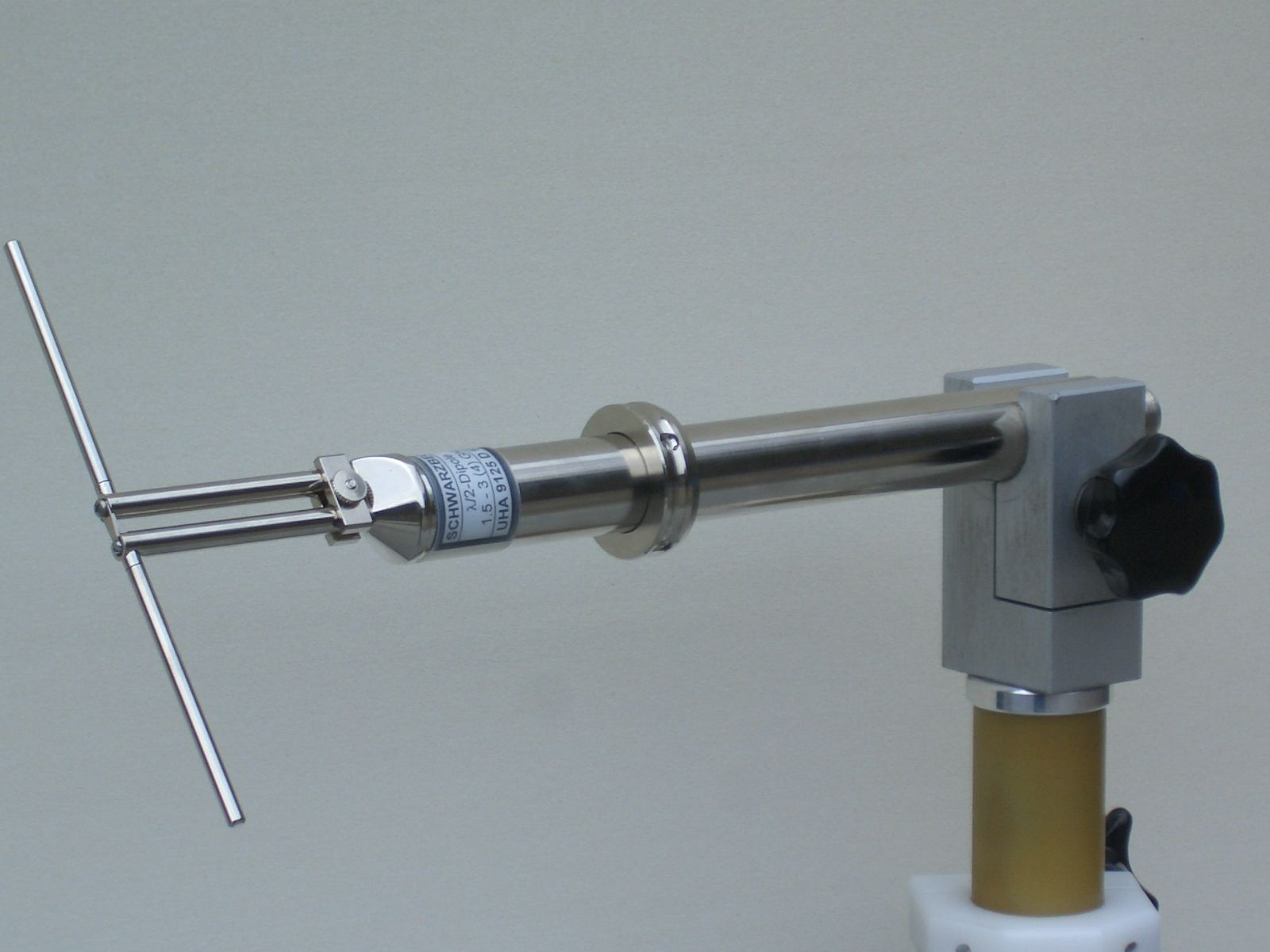
In radio and telecommunications a dipole antenna or doublet is the simplest and most widely used class of antenna. The dipole is any one of a class of antennas producing a radiation pattern approximating that of an elementary electric dipole with a radiating structure supporting a line current so energized that the current has only one node at each end. A dipole antenna commonly consists of two identical conductive elements such as metal wires or rods. The driving current from the transmitter is applied, or for receiving antennas the output signal to the receiver is taken, between the two halves of the antenna. Each side of the feedline to the transmitter or receiver is connected to one of the conductors. This contrasts with a monopole antenna, which consists of a single rod or conductor with one side of the feedline connected to it, and the other side connected to some type of ground. A common example of a dipole is the "rabbit ears" television antenna found on broadcast telev ... [...More Info...] [...Related Items...] OR: [Wikipedia] [Google] [Baidu] |
E-plane Gain Plots Of J Antenna Variations
The E-plane and H-plane are reference planes for linearly polarized waveguides, antennas and other microwave devices. In waveguide systems, as in the electric circuits, it is often desirable to be able to split the circuit power into two or more fractions. In a waveguide system, an element called a junction is used for power division. In a low frequency electrical network, it is possible to combine circuit elements in series or in parallel, thereby dividing the source power among several circuit components. In microwave circuits, a waveguide with three independent ports is called a TEE junction. The output of E-Plane Tee is 180° out of phase where the output of H-plane Tee is in phase. E-Plane For a linearly-polarized antenna, this is the plane containing the electric field vector (sometimes called the E aperture) and the direction of maximum radiation. The electric field or "E" plane determines the polarization or orientation of the radio wave. For a vertically polariz ... [...More Info...] [...Related Items...] OR: [Wikipedia] [Google] [Baidu] |
J-pole Antenna And Variations Of Same
The J-pole antenna, more properly known as the J antenna, is a vertical omnidirectional transmitting antenna used in the shortwave frequency bands. It was invented by Hans Beggerow in 1909 for use in Zeppelin airships. Trailed behind the airship, it consisted of a single one half wavelength long wire radiator, in series with a quarter-wave parallel transmission line tuning stub which matches the antenna impedance to the feedline. By 1936 this antenna began to be used for land-based transmitters with the radiating element and the matching section mounted vertically, giving it the shape of the letter "J", and was named the ''J antenna'' by 1943. When the radiating half-wave section is mounted horizontally, at right-angles to the quarter-wave matching stub, the variation is usually called a Zepp antenna. How it works The J-pole antenna is an end-fed omnidirectional half-wave antenna that is matched to the feedline by a shorted quarter-wave parallel transmission line stub. ... [...More Info...] [...Related Items...] OR: [Wikipedia] [Google] [Baidu] |
Monopole Antenna
A monopole antenna is a class of radio antenna consisting of a straight rod-shaped conductor, often mounted perpendicularly over some type of conductive surface, called a ground plane. The driving signal from the transmitter is applied, or for receiving antennas the output signal to the receiver is taken, between the lower end of the monopole and the ground plane. One side of the antenna feedline is attached to the lower end of the monopole, and the other side is attached to the ground plane, which is often the Earth. This contrasts with a dipole antenna which consists of two identical rod conductors, with the signal from the transmitter applied between the two halves of the antenna. The monopole is often used as a resonant antenna; the rod functions as an open resonator for radio waves, oscillating with standing waves of voltage and current along its length. Therefore the length of the antenna is determined by the wavelength of the radio waves it is used with. The most co ... [...More Info...] [...Related Items...] OR: [Wikipedia] [Google] [Baidu] |
Balun
A balun (from "balanced to unbalanced", originally, but now dated from "balancing unit") is an electrical device that allows balanced and unbalanced lines to be interfaced without disturbing the impedance arrangement of either line. A balun can take many forms and may include devices that also transform impedances but need not do so. Sometimes, in the case of transformer baluns, they use magnetic coupling but need not do so. Common-mode chokes are also used as baluns and work by eliminating, rather than rejecting, common mode signals. Types of balun Classical transformer type In classical transformers, there are two electrically separate windings of wire coils around the transformer's core. The advantage of transformer-type over other types of balun is that the electrically separate windings for input and output allow these baluns to connect circuits whose ground-level voltages are subject to ground loops or are otherwise electrically incompatible; for that reason they ... [...More Info...] [...Related Items...] OR: [Wikipedia] [Google] [Baidu] |
Choke (electronics)
In electronics, a choke is an inductor used to block higher-frequency alternating currents while passing direct current (DC) and lower-frequencies alternating current (AC) in an electrical circuit. A choke usually consists of a coil of insulated wire often wound on a magnetic core, although some consist of a doughnut-shaped "bead" of ferrite material strung on a wire. The choke's impedance increases with frequency. Its low electrical resistance passes both AC and DC with little power loss, but its reactance limits the amount of AC passed. The name comes from blocking—"choking"—high frequencies while passing low frequencies. It is a functional name; the name "choke" is used if an inductor is used for blocking or decoupling higher frequencies, but the component is simply called an "inductor" if used in electronic filters or tuned circuits. Inductors designed for use as chokes are usually distinguished by not having low-loss construction (high Q factor) required in inductor ... [...More Info...] [...Related Items...] OR: [Wikipedia] [Google] [Baidu] |
Coax Cable
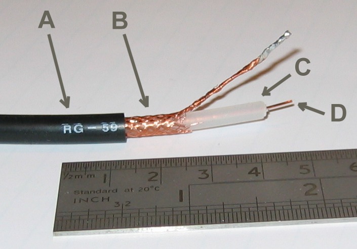
Coaxial cable, or coax (pronounced ) is a type of electrical cable consisting of an inner conductor surrounded by a concentric conducting shield, with the two separated by a dielectric ( insulating material); many coaxial cables also have a protective outer sheath or jacket. The term ''coaxial'' refers to the inner conductor and the outer shield sharing a geometric axis. Coaxial cable is a type of transmission line, used to carry high-frequency electrical signals with low losses. It is used in such applications as telephone trunk lines, broadband internet networking cables, high-speed computer data busses, cable television signals, and connecting radio transmitters and receivers to their antennas. It differs from other shielded cables because the dimensions of the cable and connectors are controlled to give a precise, constant conductor spacing, which is needed for it to function efficiently as a transmission line. Coaxial cable was used in the first (1858) and followin ... [...More Info...] [...Related Items...] OR: [Wikipedia] [Google] [Baidu] |
Twin-lead
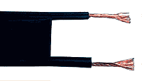
Twin-lead cable is a two-conductor flat cable used as a balanced transmission line to carry radio frequency (RF) signals. It is constructed of two stranded or solid copper or copper-clad steel wires, held a precise distance apart by a plastic (usually polyethylene) ribbon. The uniform spacing of the wires is the key to the cable's function as a transmission line; any abrupt changes in spacing would reflect some of the signal back toward the source. The plastic also covers and insulates the wires. It is available with several different values of characteristic impedance, the most common type is 300 ohm. Twin lead is mainly used as an antenna feedline at shortwave and VHF frequencies, to connect radio receivers and transmitters to their antennas. It can have significantly lower signal loss than miniature flexible coaxial cable, the main alternative type of feedline at these frequencies; for example, type RG-58 coaxial cable loses 6.6 dB per 100 m at 30 MHz, wh ... [...More Info...] [...Related Items...] OR: [Wikipedia] [Google] [Baidu] |
Ladder Line
Twin-lead cable is a two-conductor flat cable used as a balanced transmission line to carry radio frequency (RF) signals. It is constructed of two stranded or solid copper or copper-clad steel wires, held a precise distance apart by a plastic (usually polyethylene) ribbon. The uniform spacing of the wires is the key to the cable's function as a transmission line; any abrupt changes in spacing would reflect some of the signal back toward the source. The plastic also covers and insulates the wires. It is available with several different values of characteristic impedance, the most common type is 300 ohm. Twin lead is mainly used as an antenna feedline at shortwave and VHF frequencies, to connect radio receivers and transmitters to their antennas. It can have significantly lower signal loss than miniature flexible coaxial cable, the main alternative type of feedline at these frequencies; for example, type RG-58 coaxial cable loses 6.6 dB per 100 m at 30 MHz, wh ... [...More Info...] [...Related Items...] OR: [Wikipedia] [Google] [Baidu] |


