|
Sideband
In radio communications, a sideband is a band of frequencies higher than or lower than the carrier frequency, that are the result of the modulation process. The sidebands carry the information transmitted by the radio signal. The sidebands comprise all the spectral components of the modulated signal except the carrier. The signal components above the carrier frequency constitute the upper sideband (USB), and those below the carrier frequency constitute the lower sideband (LSB). All forms of modulation produce sidebands. Sideband creation We can illustrate the creation of sidebands with one trigonometric identity: :\cos(A)\cdot \cos(B) \equiv \tfrac\cos(A+B) + \tfrac\cos(A-B) Adding \cos(A) to both sides: :\cos(A)\cdot +\cos(B)= \tfrac\cos(A+B) + \cos(A) + \tfrac\cos(A-B) Substituting (for instance) A \triangleq 1000\cdot t and B \triangleq 100\cdot t, where t represents time: :\underbrace_\cdot \underbrace_ = \underbrace_ + \underbrace_ + \unde ... [...More Info...] [...Related Items...] OR: [Wikipedia] [Google] [Baidu] |
Carrier Frequency
In telecommunications, a carrier wave, carrier signal, or just carrier, is a waveform (usually sinusoidal) that is modulated (modified) with an information-bearing signal for the purpose of conveying information. This carrier wave usually has a much higher frequency than the input signal does. The purpose of the carrier is usually either to transmit the information through space as an electromagnetic wave (as in radio communication), or to allow several carriers at different frequencies to share a common physical transmission medium by frequency division multiplexing (as in a cable television system). The term originated in radio communication, where the carrier wave creates the waves which carry the information (modulation) through the air from the transmitter to the receiver. The term is also used for an unmodulated emission in the absence of any modulating signal. In music production, carrier signals can be controlled by a modulating signal to change the sound property of an ... [...More Info...] [...Related Items...] OR: [Wikipedia] [Google] [Baidu] |
Quadrature Amplitude Modulation
Quadrature amplitude modulation (QAM) is the name of a family of digital modulation methods and a related family of analog modulation methods widely used in modern telecommunications to transmit information. It conveys two analog message signals, or two digital bit streams, by changing (''modulating'') the amplitudes of two carrier waves, using the amplitude-shift keying (ASK) digital modulation scheme or amplitude modulation (AM) analog modulation scheme. The two carrier waves are of the same frequency and are out of phase with each other by 90°, a condition known as orthogonality or quadrature. The transmitted signal is created by adding the two carrier waves together. At the receiver, the two waves can be coherently separated (demodulated) because of their orthogonality property. Another key property is that the modulations are low-frequency/low-bandwidth waveforms compared to the carrier frequency, which is known as the narrowband assumption. Phase modulation (analog PM) ... [...More Info...] [...Related Items...] OR: [Wikipedia] [Google] [Baidu] |
Subcarrier
A subcarrier is a sideband of a radio frequency carrier wave, which is modulated to send additional information. Examples include the provision of colour in a black and white television system or the provision of stereo in a monophonic radio broadcast. There is no physical difference between a carrier and a subcarrier; the "sub" implies that it has been derived from a carrier, which has been amplitude modulated by a steady signal and has a constant frequency relation to it. FM stereo Stereo broadcasting is made possible by using a subcarrier on FM radio stations, which takes the left channel and "subtracts" the right channel from it — essentially by hooking up the right-channel wires backward (reversing polarity) and then joining left and reversed-right. The result is modulated with suppressed carrier AM, more correctly called sum and difference modulation or SDM, at 38 kHz in the FM signal, which is joined at 2% modulation with the mono left+right audio (which ran ... [...More Info...] [...Related Items...] OR: [Wikipedia] [Google] [Baidu] |
Double-sideband Suppressed-carrier Transmission
Double-sideband suppressed-carrier transmission (DSB-SC) is transmission in which frequencies produced by amplitude modulation (AM) are symmetrically spaced above and below the carrier frequency and the carrier level is reduced to the lowest practical level, ideally being completely suppressed. In the DSB-SC modulation, unlike in AM, the wave carrier is not transmitted; thus, much of the power is distributed between the side bands, which implies an increase of the cover in DSB-SC, compared to AM, for the same power use. DSB-SC transmission is a special case of double-sideband reduced carrier transmission. It is used for radio data systems. This mode is frequently used in Amateur radio voice communications, especially on High-Frequency bands. Spectrum DSB-SC is basically an amplitude modulation Amplitude modulation (AM) is a modulation technique used in electronic communication, most commonly for transmitting messages with a radio wave. In amplitude modulation, the amp ... [...More Info...] [...Related Items...] OR: [Wikipedia] [Google] [Baidu] |
Carrier Signal
In telecommunications, a carrier wave, carrier signal, or just carrier, is a waveform (usually sinusoidal) that is modulated (modified) with an information-bearing signal for the purpose of conveying information. This carrier wave usually has a much higher frequency than the input signal does. The purpose of the carrier is usually either to transmit the information through space as an electromagnetic wave (as in radio communication), or to allow several carriers at different frequencies to share a common physical transmission medium by frequency division multiplexing (as in a cable television system). The term originated in radio communication, where the carrier wave creates the waves which carry the information (modulation) through the air from the transmitter to the receiver. The term is also used for an unmodulated emission in the absence of any modulating signal. In music production, carrier signals can be controlled by a modulating signal to change the sound property of ... [...More Info...] [...Related Items...] OR: [Wikipedia] [Google] [Baidu] |
Double-sideband Reduced-carrier Transmission
Double-sideband reduced carrier transmission (DSB-RC): transmission in which (a) the frequencies produced by amplitude modulation are symmetrically spaced above and below the carrier and (b) the carrier level is reduced for transmission at a fixed level below that which is provided to the modulator. ''Note:'' In DSB-RC transmission, the carrier is usually transmitted at a level suitable for use as a reference by the receiver, except for the case in which it is reduced to the minimum practical level, i.e. the carrier is suppressed. See also *Double-sideband suppressed-carrier transmission Double-sideband suppressed-carrier transmission (DSB-SC) is transmission in which frequencies produced by amplitude modulation (AM) are symmetrically spaced above and below the carrier frequency and the carrier level is reduced to the lowest pra ... References * Radio modulation modes {{telecomm-stub ... [...More Info...] [...Related Items...] OR: [Wikipedia] [Google] [Baidu] |
Envelope Detector
An envelope detector (sometimes called a peak detector) is an electronic circuit that takes a (relatively) high-frequency amplitude modulated signal as input and provides an output, which is the demodulated ''envelope'' of the original signal. Circuit operation The capacitor in the circuit above stores charge on the rising edge and releases it slowly through the resistor when the input signal amplitude falls. The diode in series rectifies the incoming signal, allowing current flow only when the positive input terminal is at a higher potential than the negative input terminal. General considerations Most practical envelope detectors use either half-wave or full-wave rectification of the signal to convert the AC audio input into a pulsed DC signal. Filtering is then used to smooth the final result. This filtering is rarely perfect and some "ripple" is likely to remain on the envelope follower output, particularly for low frequency inputs such as notes from a bass instrum ... [...More Info...] [...Related Items...] OR: [Wikipedia] [Google] [Baidu] |
Costas Loop
A Costas loop is a phase-locked loop (PLL) based circuit which is used for carrier frequency recovery from suppressed-carrier modulation signals (e.g. double-sideband suppressed carrier signals) and phase modulation signals (e.g. BPSK, QPSK). It was invented by John P. Costas at General Electric in the 1950s. Its invention was described as having had "a profound effect on modern digital communications". The primary application of Costas loops is in wireless receivers. Its advantage over other PLL-based detectors is that at small deviations the Costas loop error voltage is \sin(2(\theta_i-\theta_f)) as compared to \sin(\theta_i-\theta_f). This translates to double the sensitivity and also makes the Costas loop uniquely suited for tracking Doppler-shifted carriers, especially in OFDM and GPS receivers. Classical implementation In the classical implementation of a Costas loop, a local voltage-controlled oscillator (VCO) provides quadrature outputs, one to each of two phase dete ... [...More Info...] [...Related Items...] OR: [Wikipedia] [Google] [Baidu] |
Analog Television
Analog television is the original television technology that uses analog signals to transmit video and audio. In an analog television broadcast, the brightness, colors and sound are represented by amplitude, instantaneous phase and frequency, phase and frequency of an analog signal. Analog signals vary over a continuous range of possible values which means that Noise (electronics), electronic noise and interference may be introduced. Thus with analog, a moderately weak signal becomes Noise (video), snowy and subject to interference. In contrast, picture quality from a digital television (DTV) signal remains good until the signal level drops below digital cliff, a threshold where reception is no longer possible or becomes intermittent. Analog television may be wireless (terrestrial television and satellite television) or can be distributed over a cable network as cable television. All broadcast television systems used analog signals before the arrival of DTV. Motivated by the ... [...More Info...] [...Related Items...] OR: [Wikipedia] [Google] [Baidu] |
Pilot Signal
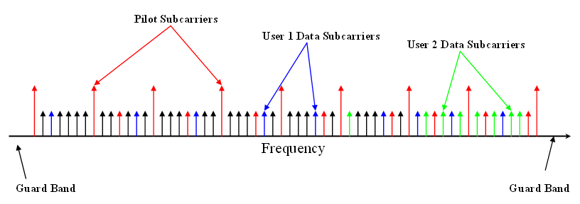
In telecommunications, a pilot signal is a signal, usually a single frequency, transmitted over a communications system for supervisory, control, equalization, continuity, synchronization, or reference purposes. Uses in different communication systems FM Radio In FM stereo broadcasting, a pilot tone of 19 kHz indicates that there is stereophonic information at 38 kHz (the second harmonic of the pilot tone). The receiver doubles the frequency of the pilot tone and uses it as a frequency and phase reference to demodulate the stereo information. If no 19 kHz pilot tone is present, then any signals in the 23–53 kHz range are ignored by a stereo receiver. A guard band of ±4 kHz (15–23 kHz) protects the pilot tone from interference from the baseband audio signal (50 Hz–15 kHz) and from the lower sideband of the double sideband stereo information (23–53 kHz). The third harmonic of the pilot (57 kHz) is used for Radio Data System. The fourth harmonic (76 kHz) is used for ... [...More Info...] [...Related Items...] OR: [Wikipedia] [Google] [Baidu] |
FM Broadcasting
FM broadcasting is a method of radio broadcasting using frequency modulation (FM). Invented in 1933 by American engineer Edwin Armstrong, wide-band FM is used worldwide to provide high fidelity sound over broadcast radio. FM broadcasting is capable of higher fidelity—that is, more accurate reproduction of the original program sound—than other broadcasting technologies, such as AM broadcasting. It is also less susceptible to common forms of interference, reducing static and popping sounds often heard on AM. Therefore, FM is used for most broadcasts of music or general audio (in the audio spectrum). FM radio stations use the very high frequency range of radio frequencies. Broadcast bands Throughout the world, the FM broadcast band falls within the VHF part of the radio spectrum. Usually 87.5 to 108.0 MHz is used, or some portion thereof, with few exceptions: * In the former Soviet republics, and some former Eastern Bloc countries, the older 65.8–74 MHz band ... [...More Info...] [...Related Items...] OR: [Wikipedia] [Google] [Baidu] |


