|
Semiconductor Characterization Techniques
{{Use mdy dates, date = March 2019 Semiconductor characterization techniques are used to characterize a semiconductor material or device ( PN junction, Schottky diode, etc.). Some examples of semiconductor properties that could be characterized include the depletion width, carrier concentration, carrier generation and recombination rates, carrier lifetimes, defect concentration, and trap states. Electrical characterization techniques Electrical characterization can be used to determine resistivity, carrier concentration, mobility, contact resistance, barrier height, depletion width, oxide charge, interface states, carrier lifetimes, and deep level impurities. * Two-point probe * Four-point probe * Differential Hall effect * Capacitance voltage profiling * Deep-level transient spectroscopy (DLTS) * Electron beam-induced current * Drive-level capacitance profiling (DLCP) Optical characterization techniques * Microscopy * Ellipsometry * Photoluminescence * Absorption or tra ... [...More Info...] [...Related Items...] OR: [Wikipedia] [Google] [Baidu] |
Characterization (materials Science)
Characterization, when used in materials science, refers to the broad and general process by which a material's structure and properties are probed and measured. It is a fundamental process in the field of materials science, without which no scientific understanding of engineering materials could be ascertained. The scope of the term often differs; some definitions limit the term's use to techniques which study the microscopic structure and properties of materials, while others use the term to refer to any materials analysis process including macroscopic techniques such as mechanical testing, thermal analysis and density calculation. The scale of the structures observed in materials characterization ranges from angstroms, such as in the imaging of individual atoms and chemical bonds, up to centimeters, such as in the imaging of coarse grain structures in metals. While many characterization techniques have been practiced for centuries, such as basic optical microscopy, new techniq ... [...More Info...] [...Related Items...] OR: [Wikipedia] [Google] [Baidu] |
Microscopy
Microscopy is the technical field of using microscopes to view objects and areas of objects that cannot be seen with the naked eye (objects that are not within the resolution range of the normal eye). There are three well-known branches of microscopy: optical, electron, and scanning probe microscopy, along with the emerging field of X-ray microscopy. Optical microscopy and electron microscopy involve the diffraction, reflection, or refraction of electromagnetic radiation/electron beams interacting with the specimen, and the collection of the scattered radiation or another signal in order to create an image. This process may be carried out by wide-field irradiation of the sample (for example standard light microscopy and transmission electron microscopy) or by scanning a fine beam over the sample (for example confocal laser scanning microscopy and scanning electron microscopy). Scanning probe microscopy involves the interaction of a scanning probe with the surface of the ... [...More Info...] [...Related Items...] OR: [Wikipedia] [Google] [Baidu] |
Ion Beam
An ion beam is a type of charged particle beam consisting of ions. Ion beams have many uses in electronics manufacturing (principally ion implantation) and other industries. A variety of ion beam sources exists, some derived from the mercury vapor thrusters developed by NASA in the 1960s. The most common ion beams are of singly-charged ions. Units Ion current density is typically measured in mA/cm^2, and ion energy in eV. The use of eV is convenient for converting between voltage and energy, especially when dealing with singly-charged ion beams, as well as converting between energy and temperature (1 eV = 11600 K). Broad-beam ion sources Most commercial applications use two popular types of ion source, gridded and gridless, which differ in current and power characteristics and the ability to control ion trajectories. In both cases electrons are needed to generate an ion beam. The most common electron emitters are hot filament and hollow cathode. Gridded ion source In ... [...More Info...] [...Related Items...] OR: [Wikipedia] [Google] [Baidu] |
Electron Energy Loss Spectroscopy
In electron energy loss spectroscopy (EELS) a material is exposed to a beam of electrons with a known, narrow range of kinetic energies. Some of the electrons will undergo inelastic scattering, which means that they lose energy and have their paths slightly and randomly deflected. The amount of energy loss can be measured via an electron spectrometer and interpreted in terms of what caused the energy loss. Inelastic interactions include phonon excitations, inter- and intra-band transitions, plasmon excitations, inner shell ionizations, and Cherenkov radiation. The inner-shell ionizations are particularly useful for detecting the elemental components of a material. For example, one might find that a larger-than-expected number of electrons comes through the material with 285 eV less energy than they had when they entered the material. This is approximately the amount of energy needed to remove an inner-shell electron from a carbon atom, which can be taken as evidence t ... [...More Info...] [...Related Items...] OR: [Wikipedia] [Google] [Baidu] |
Electron Microprobe
An electron microprobe (EMP), also known as an electron probe microanalyzer (EPMA) or electron micro probe analyzer (EMPA), is an analytical tool used to non-destructively determine the chemical composition of small volumes of solid materials. It works similarly to a scanning electron microscope: the sample is bombarded with an electron beam, emitting x-rays at wavelengths characteristic to the elements being analyzed. This enables the abundances of elements present within small sample volumes (typically 10-30 cubic micrometers or less) to be determined,Wittry, David B. (1958). "Electron Probe Microanalyzer"US Patent No 2916621 Washington, DC: U.S. Patent and Trademark Office when a conventional accelerating voltage of 15-20 kV is used. The concentrations of elements from lithium to plutonium may be measured at levels as low as 100 parts per million (ppm), material dependent, although with care, levels below 10 ppm are possible. The ability to quantify lithium by EPMA became a re ... [...More Info...] [...Related Items...] OR: [Wikipedia] [Google] [Baidu] |
Auger Electron Spectroscopy
A Hanford scientist uses an Auger electron spectrometer to determine the elemental composition of surfaces. Auger electron spectroscopy (AES; pronounced in French) is a common analytical technique used specifically in the study of surfaces and, more generally, in the area of materials science. It is a form of electron spectroscopy that relies on the Auger effect, based on the analysis of energetic electrons emitted from an excited atom after a series of internal relaxation events. The Auger effect was discovered independently by both Lise Meitner and Pierre Auger in the 1920s. Though the discovery was made by Meitner and initially reported in the journal ''Zeitschrift für Physik'' in 1922, Auger is credited with the discovery in most of the scientific community. Until the early 1950s Auger transitions were considered nuisance effects by spectroscopists, not containing much relevant material information, but studied so as to explain anomalies in X-ray spectroscopy data. Since 19 ... [...More Info...] [...Related Items...] OR: [Wikipedia] [Google] [Baidu] |
Transmission Electron Microscopy
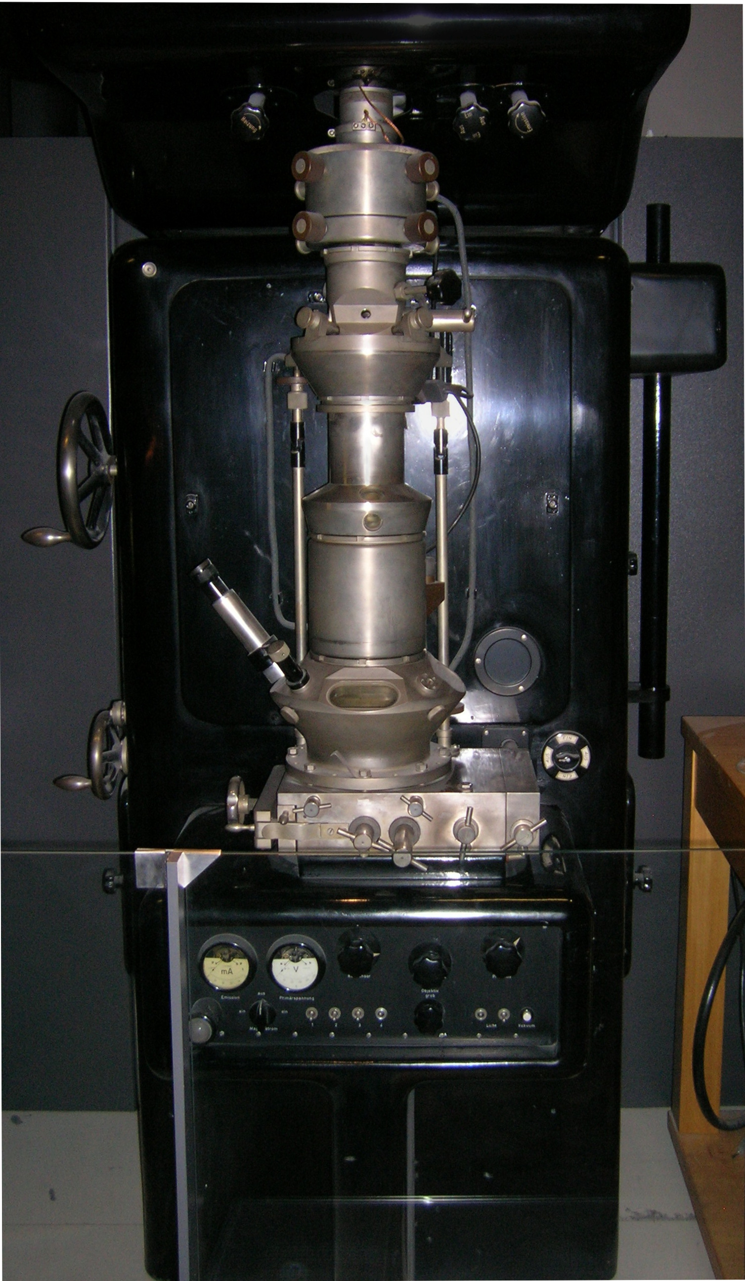
Transmission electron microscopy (TEM) is a microscopy technique in which a beam of electrons is transmitted through a specimen to form an image. The specimen is most often an ultrathin section less than 100 nm thick or a suspension on a grid. An image is formed from the interaction of the electrons with the sample as the beam is transmitted through the specimen. The image is then magnified and focused onto an imaging device, such as a fluorescent screen, a layer of photographic film, or a sensor such as a scintillator attached to a charge-coupled device. Transmission electron microscopes are capable of imaging at a significantly higher resolution than light microscopes, owing to the smaller de Broglie wavelength of electrons. This enables the instrument to capture fine detail—even as small as a single column of atoms, which is thousands of times smaller than a resolvable object seen in a light microscope. Transmission electron microscopy is a major analytical method ... [...More Info...] [...Related Items...] OR: [Wikipedia] [Google] [Baidu] |
Electron Beam
Cathode rays or electron beam (e-beam) are streams of electrons observed in discharge tubes. If an evacuated glass tube is equipped with two electrodes and a voltage is applied, glass behind the positive electrode is observed to glow, due to electrons emitted from the cathode (the electrode connected to the negative terminal of the voltage supply). They were first observed in 1859 by German physicist Julius Plücker and Johann Wilhelm Hittorf, and were named in 1876 by Eugen Goldstein ''Kathodenstrahlen'', or cathode rays. In 1897, British physicist J. J. Thomson showed that cathode rays were composed of a previously unknown negatively charged particle, which was later named the ''electron''. Cathode-ray tubes (CRTs) use a focused beam of electrons deflected by electric or magnetic fields to render an image on a screen. Description Cathode rays are so named because they are emitted by the negative electrode, or cathode, in a vacuum tube. To release electrons into the tube, th ... [...More Info...] [...Related Items...] OR: [Wikipedia] [Google] [Baidu] |
Cathodoluminescence
Cathodoluminescence is an optical and electromagnetic phenomenon in which electrons impacting on a luminescent material such as a phosphor, cause the emission of photons which may have wavelengths in the visible spectrum. A familiar example is the generation of light by an electron beam scanning the phosphor-coated inner surface of the screen of a television that uses a cathode ray tube. Cathodoluminescence is the inverse of the photoelectric effect, in which electron emission is induced by irradiation with photons. Origin Luminescence in a semiconductor results when an electron in the conduction band recombines with a hole in the valence band. The difference energy (band gap) of this transition can be emitted in form of a photon. The energy (color) of the photon, and the probability that a photon and not a phonon will be emitted, depends on the material, its purity, and the presence of defects. First, the electron has to be excited from the valence band into the conduction b ... [...More Info...] [...Related Items...] OR: [Wikipedia] [Google] [Baidu] |
Reflectance
The reflectance of the surface of a material is its effectiveness in Reflection (physics), reflecting radiant energy. It is the fraction of incident electromagnetic power that is reflected at the boundary. Reflectance is a component of the response of the electronic structure of the material to the electromagnetic field of light, and is in general a function of the frequency, or wavelength, of the light, its polarization, and the angle of incidence (optics), angle of incidence. The dependence of reflectance on the wavelength is called a ''reflectance spectrum'' or ''spectral reflectance curve''. Mathematical definitions Hemispherical reflectance The ''hemispherical reflectance'' of a surface, denoted , is defined as R = \frac, where is the radiant flux ''reflected'' by that surface and is the radiant flux ''received'' by that surface. Spectral hemispherical reflectance The ''spectral hemispherical reflectance in frequency'' and ''spectral hemispherical reflectance in wavelength ... [...More Info...] [...Related Items...] OR: [Wikipedia] [Google] [Baidu] |
Raman Spectroscopy
Raman spectroscopy () (named after Indian physicist C. V. Raman) is a spectroscopic technique typically used to determine vibrational modes of molecules, although rotational and other low-frequency modes of systems may also be observed. Raman spectroscopy is commonly used in chemistry to provide a structural fingerprint by which molecules can be identified. Raman spectroscopy relies upon inelastic scattering of photons, known as Raman scattering. A source of monochromatic light, usually from a laser in the visible, near infrared, or near ultraviolet range is used, although X-rays can also be used. The laser light interacts with molecular vibrations, phonons or other excitations in the system, resulting in the energy of the laser photons being shifted up or down. The shift in energy gives information about the vibrational modes in the system. Infrared spectroscopy typically yields similar yet complementary information. Typically, a sample is illuminated with a laser beam ... [...More Info...] [...Related Items...] OR: [Wikipedia] [Google] [Baidu] |


.png)

