|
Seebach-Wettingen Railway Electrification Trial
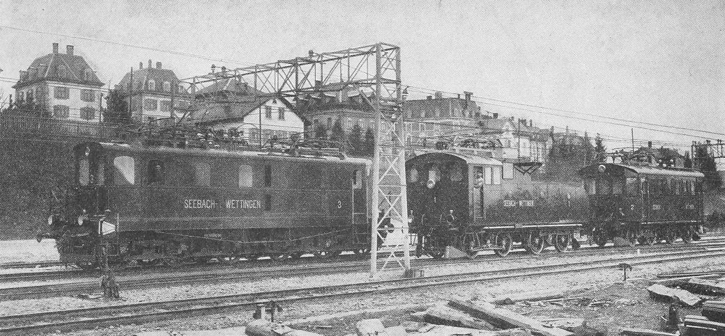
The Seebach-Wettingen railway electrification trial (1905-1909) was an important milestone in the development of electric railways. Maschinenfabrik Oerlikon (MFO) demonstrated the suitability of single-phase alternating current at high voltage for long-distance railway operation with the Seebach-Wettingen single-phase alternating current test facility. For this purpose, MFO electrified the 19.45-kilometre-long Swiss Federal Railways (SBB) route from Seebach to Wettingen at its own expense with single-phase alternating current at 15,000 volts. Overview By 1900, the use of direct current (DC), usually at 500-600 volts, to supply power to electric trams and trains was well-established. Examples include Trams in Budapest (from 1887) and the Liverpool Overhead Railway (opened 1893). This was satisfactory for urban systems but, for long distance railways, a higher voltage was desirable to reduce energy losses. The 106 km Valtellina line in Italy was electrified using three ... [...More Info...] [...Related Items...] OR: [Wikipedia] [Google] [Baidu] |
Kálmán Kandó
Kálmán Kandó de Egerfarmos et Sztregova (''egerfarmosi és sztregovai Kandó Kálmán''; 10 July 1869 – 13 January 1931) was a Hungarian engineer, the inventor of phase converter and a pioneer in the development of AC electric railway traction. Education and Family Kálmán Kandó was born on July 8, 1869 in Pest into an ancient Hungarian noble family. His father was Géza Kandó (1840-1906) his mother was Irma Gulácsy (1845-1933). He began his grammar school studies at the Budapest Lutheran High School, at the Sütő street. His parents transferred him from a crowded school to a smaller school, a practice grammar school founded by Mór Kármán. He was enrolled in Budapest Technical University. In 1892 he received a degree in mechanical engineering. He completed his studies with excellent qualifications. He successfully used his knowledge of mechanics and electricity later in his career. Kandó served as a volunteer for the Austro-Hungarian Navy until 1893. Kálmán Kand ... [...More Info...] [...Related Items...] OR: [Wikipedia] [Google] [Baidu] |
Twisted Pair
Twisted pair cabling is a type of wiring used for communications in which two conductors of a single circuit are twisted together for the purposes of improving electromagnetic compatibility. Compared to a single conductor or an untwisted balanced pair, a twisted pair reduces electromagnetic radiation from the pair and crosstalk between neighboring pairs and improves rejection of external electromagnetic interference. It was invented by Alexander Graham Bell. For additional noise immunity, twisted-pair cabling may be shielded. Cable with shielding is known as shielded twisted pair (STP) and without as unshielded twisted pair (UTP). Explanation A twisted pair can be used as a balanced line, which as part of a balanced circuit can greatly reduce the effect of noise currents induced on the line by coupling of electric or magnetic fields. The idea is that the currents induced in each of the two wires are very nearly equal. The twisting ensures that the two wires are on ave ... [...More Info...] [...Related Items...] OR: [Wikipedia] [Google] [Baidu] |
Hans Behn-Eschenburg
Hans Behn-Eschenburg (10 January 1864 – 18 May 1938) was born in Obertrass (now Zurich), Switzerland. His work on the AC single-phase motor was important to the electrification of railways. He studied mathematics and physics in Zurich and Berlin between 1886 and 1890. In 1892, Behn-Eschenburg worked at Maschinenfabrik Oerlikon, where he became chief electrician (1897-1911), director (1911–1913), director General Technical (1913-1928) and Administrative Counselor (1919-1938). Oerlikon was prominent in the construction of single-phase motors with commutators for traction. He died on 18 May 1938 in Küsnacht. His work focussed on alternating current technology, including the asynchronous motor An induction motor or asynchronous motor is an AC electric motor in which the electric current in the rotor needed to produce torque is obtained by electromagnetic induction from the magnetic field of the stator winding. An induction motor c ... and the AC single-phase motor. wh ... [...More Info...] [...Related Items...] OR: [Wikipedia] [Google] [Baidu] |
Traction Motor
A traction motor is an electric motor used for propulsion of a vehicle, such as locomotives, electric vehicle, electric or hydrogen vehicles, elevators or electric multiple unit. Traction motors are used in electrically powered rail vehicles (electric multiple units) and other electric vehicles including electric milk floats, elevators, roller coasters, conveyors, and trolleybuses, as well as vehicles with electrical transmission systems (Diesel locomotive#Transmission types, diesel-electric locomotives, electric hybrid vehicles), and battery electric vehicles. Motor types and control DC motor, Direct-current motors with series Field coil, field windings are the oldest type of traction motors. These provide a speed-torque characteristic useful for propulsion, providing high torque at lower speeds for acceleration of the vehicle, and declining torque as speed increases. By arranging the field winding with multiple taps, the speed characteristic can be varied, allowing relatively ... [...More Info...] [...Related Items...] OR: [Wikipedia] [Google] [Baidu] |
Traction Substation
A traction substation, traction current converter plant, rectifier station or traction power substation (TPSS) is an electrical substation that converts electric power from the form provided by the electrical power industry for public utility service to an appropriate voltage, current type and frequency to supply railways, trams (streetcars) or trolleybuses with traction current. Conversions These systems can be used to convert three-phase 50 Hz or 60 Hz alternating current (AC) for the supply of AC railway electrification systems at a lower frequency and single phase, as used by many older systems, or to rectify AC into direct current (DC) for those systems (primarily public transit systems) using DC for traction power. The three-phase voltage from the local utility is stepped down and rectified in the traction substations to provide the required DC voltage. Equipment Rotating Originally, the conversion equipment usually consisted of one or more motor-generator sets contain ... [...More Info...] [...Related Items...] OR: [Wikipedia] [Google] [Baidu] |
Pantograph (transport)
A pantograph (or "pan" or "panto") is an apparatus mounted on the roof of an electric train, tram or electric bus to collect power through contact with an overhead line. By contrast, battery electric buses and trains are charged at charging stations. The pantograph is a common type of current collector; typically, a single or double wire is used, with the return current running through the rails. The term stems from the resemblance of some styles to the mechanical pantographs used for copying handwriting and drawings. Invention The pantograph, with a low-friction, replaceable graphite contact strip or "shoe" to minimise lateral stress on the contact wire, first appeared in the late 19th century. Early versions include the bow collector, invented in 1889 by Walter Reichel, chief engineer at Siemens & Halske in Germany, and a flat slide-pantograph first used in 1895 by the Baltimore and Ohio Railroad The familiar diamond-shaped roller pantograph was devised and patented b ... [...More Info...] [...Related Items...] OR: [Wikipedia] [Google] [Baidu] |
Overhead Line
An overhead line or overhead wire is an electrical cable that is used to transmit electrical energy to electric locomotives, trolleybuses or trams. It is known variously as: * Overhead catenary * Overhead contact system (OCS) * Overhead equipment (OHE) * Overhead line equipment (OLE or OHLE) * Overhead lines (OHL) * Overhead wiring (OHW) * Traction wire * Trolley wire This article follows the International Union of Railways in using the generic term ''overhead line''. An overhead line consists of one or more wires (or rails, particularly in tunnels) situated over rail tracks, raised to a high electrical potential by connection to feeder stations at regular intervals. The feeder stations are usually fed from a high-voltage electrical grid. Overview Electric trains that collect their current from overhead lines use a device such as a pantograph, bow collector or trolley pole. It presses against the underside of the lowest overhead wire, the contact wire. Current collectors ar ... [...More Info...] [...Related Items...] OR: [Wikipedia] [Google] [Baidu] |
Rotary Converter
A rotary converter is a type of electrical machine which acts as a mechanical rectifier, inverter or frequency converter. Rotary converters were used to convert alternating current (AC) to direct current (DC), or DC to AC power, before the advent of chemical or solid state power rectification and inverting. They were commonly used to provide DC power for commercial, industrial and railway electrification from an AC power source. Principles of operation The rotary converter can be thought of as a motor-generator, where the two machines share a single rotating armature and set of field coils. The basic construction of the rotary converter consists of a DC generator (dynamo) with a set of slip rings tapped into its rotor windings at evenly spaced intervals. When a dynamo is spun the electric currents in its rotor windings alternate as it rotates in the magnetic field of the stationary field windings. This alternating current is rectified by means of a commutator, which all ... [...More Info...] [...Related Items...] OR: [Wikipedia] [Google] [Baidu] |
Utility Frequency
The utility frequency, (power) line frequency (American English) or mains frequency (British English) is the nominal frequency of the oscillations of alternating current (AC) in a wide area synchronous grid transmitted from a power station to the end-user. In large parts of the world this is 50 Hz, although in the Americas and parts of Asia it is typically 60 Hz. Current usage by country or region is given in the list of mains electricity by country. During the development of commercial electric power systems in the late-19th and early-20th centuries, many different frequencies (and voltages) had been used. Large investment in equipment at one frequency made standardization a slow process. However, as of the turn of the 21st century, places that now use the 50 Hz frequency tend to use 220–240 V, and those that now use 60 Hz tend to use 100–127 V. Both frequencies coexist today (Japan uses both) with no great technical reason to prefer one over ... [...More Info...] [...Related Items...] OR: [Wikipedia] [Google] [Baidu] |
Commutator (electric)
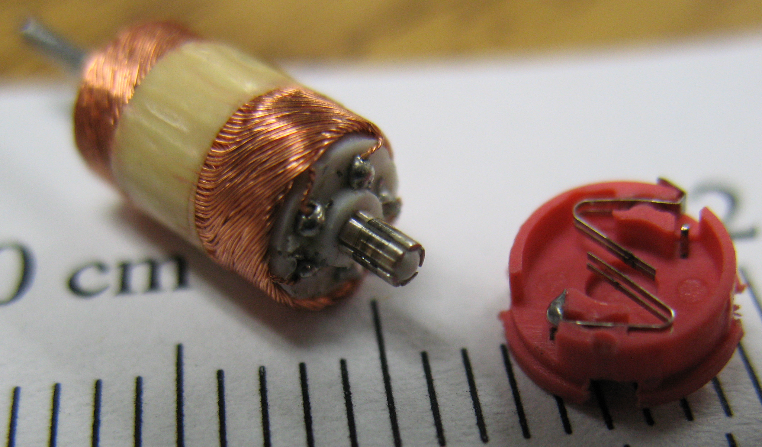
A commutator is a rotary electrical switch in certain types of electric motors and electrical generators that periodically reverses the current direction between the rotor and the external circuit. It consists of a cylinder composed of multiple metal contact segments on the rotating armature of the machine. Two or more electrical contacts called " brushes" made of a soft conductive material like carbon press against the commutator, making sliding contact with successive segments of the commutator as it rotates. The windings (coils of wire) on the armature are connected to the commutator segments. Commutators are used in direct current (DC) machines: dynamos (DC generators) and many DC motors as well as universal motors. In a motor the commutator applies electric current to the windings. By reversing the current direction in the rotating windings each half turn, a steady rotating force (torque) is produced. In a generator the commutator picks off the current generated in ... [...More Info...] [...Related Items...] OR: [Wikipedia] [Google] [Baidu] |
Universal Motor
The universal motor is a type of electric motor that can operate on either AC or DC power and uses an electromagnet as its stator to create its magnetic field. It is a commutated series-wound motor where the stator's field coils are connected in series with the rotor windings through a commutator. It is often referred to as an AC series motor. The universal motor is very similar to a DC series motor in construction, but is modified slightly to allow the motor to operate properly on AC power. This type of electric motor can operate well on AC because the current in both the field coils and the armature (and the resultant magnetic fields) will alternate (reverse polarity) synchronously with the supply. Hence the resulting mechanical force will occur in a consistent direction of rotation, independent of the direction of applied voltage, but determined by the commutator and polarity of the field coils.Herman, Stephen L. ''Delmar's Standard Textbook of Electricity, 3rd Edition.'' Clif ... [...More Info...] [...Related Items...] OR: [Wikipedia] [Google] [Baidu] |


.jpg)
.jpg)
