|
Schematic Of Typical Two-dimensional Infrared Spectrum
A schematic, or schematic diagram, is a designed representation of the elements of a system using abstract, graphic symbols rather than realistic pictures. A schematic usually omits all details that are not relevant to the key information the schematic is intended to convey, and may include oversimplified elements in order to make this essential meaning easier to grasp, as well as additional organization of the information. For example, a subway map intended for passengers may represent a subway station with a dot. The dot is not intended to resemble the actual station at all but aims to give the viewer information without unnecessary visual clutter. A schematic diagram of a chemical process uses symbols in place of detailed representations of the vessels, piping, valves, pumps, and other equipment that compose the system, thus emphasizing the functions of the individual elements and the interconnections among them and suppresses their physical details. In an electronic circuit d ... [...More Info...] [...Related Items...] OR: [Wikipedia] [Google] [Baidu] |
Photomicrograph
A micrograph or photomicrograph is a photograph or digital image taken through a microscope or similar device to show a magnified image of an object. This is opposed to a macrograph or photomacrograph, an image which is also taken on a microscope but is only slightly magnified, usually less than 10 times. Micrography is the practice or art of using microscopes to make photographs. A micrograph contains extensive details of microstructure. A wealth of information can be obtained from a simple micrograph like behavior of the material under different conditions, the phases found in the system, failure analysis, grain size estimation, elemental analysis and so on. Micrographs are widely used in all fields of microscopy. Types Photomicrograph A light micrograph or photomicrograph is a micrograph prepared using an optical microscope, a process referred to as ''photomicroscopy''. At a basic level, photomicroscopy may be performed simply by connecting a camera to a microscope, th ... [...More Info...] [...Related Items...] OR: [Wikipedia] [Google] [Baidu] |
Hardware Description Language
In computer engineering, a hardware description language (HDL) is a specialized computer language used to describe the structure and behavior of electronic circuits, and most commonly, digital logic circuits. A hardware description language enables a precise, formal description of an electronic circuit that allows for the automated analysis and simulation of an electronic circuit. It also allows for the synthesis of an HDL description into a netlist (a specification of physical electronic components and how they are connected together), which can then be placed and routed to produce the set of masks used to create an integrated circuit. A hardware description language looks much like a programming language such as C or ALGOL; it is a textual description consisting of expressions, statements and control structures. One important difference between most programming languages and HDLs is that HDLs explicitly include the notion of time. HDLs form an integral part of electr ... [...More Info...] [...Related Items...] OR: [Wikipedia] [Google] [Baidu] |
Energy Systems Language
The Energy Systems Language, also referred to as Energese, Energy Circuit Language, or Generic Systems Symbols, is a modelling language used for composing energy flow diagrams in the field of systems ecology. It was developed by Howard T. Odum and colleagues in the 1950s during studies of the tropical forests funded by the United States Atomic Energy Commission. Design intent The design intent of the energy systems language was to facilitate the generic depiction of energy flows through any scale system while encompassing the laws of physics, and in particular, the laws of thermodynamics (see energy transformation for an example). In particular H.T. Odum aimed to produce a language which could facilitate the intellectual analysis, engineering synthesis and management of global systems such as the geobiosphere, and its many subsystems. Within this aim, H.T. Odum had a strong concern that many abstract mathematical models of such systems were not thermodynamically valid. Hence he ... [...More Info...] [...Related Items...] OR: [Wikipedia] [Google] [Baidu] |
Repairing
The technical meaning of maintenance involves functional checks, servicing, repairing or replacing of necessary devices, equipment, machinery, building infrastructure, and supporting utilities in industrial, business, and residential installations. Over time, this has come to include multiple wordings that describe various cost-effective practices to keep equipment operational; these activities occur either before or after a failure. Definitions Maintenance functions can defined as maintenance, repair and overhaul (MRO), and MRO is also used for maintenance, repair and operations. Over time, the terminology of maintenance and MRO has begun to become standardized. The United States Department of Defense uses the following definitions:Federal Standard 1037C and from MIL-STD-188 and from the Department of Defense Dictionary of Military and Associated Terms * Any activity—such as tests, measurements, replacements, adjustments, and repairs—intended to retain or restore a fun ... [...More Info...] [...Related Items...] OR: [Wikipedia] [Google] [Baidu] |
Symmetrical Components
In electrical engineering, the method of symmetrical components simplifies analysis of unbalanced three-phase power systems under both normal and abnormal conditions. The basic idea is that an asymmetrical set of ''N'' phasors can be expressed as a linear combination of ''N'' symmetrical sets of phasors by means of a complex linear transformation. Fortescue's theorem (symmetrical components) is based on superposition principle, so it is applicable to linear power systems only, or to linear approximations of non-linear power systems. In the most common case of three-phase systems, the resulting "symmetrical" components are referred to as ''direct'' (or ''positive''), ''inverse'' (or ''negative'') and ''zero'' (or ''homopolar''). The analysis of power system is much simpler in the domain of symmetrical components, because the resulting equations are mutually linearly independent if the circuit itself is balanced. Description In 1918 Charles Legeyt Fortescue presented a paper which ... [...More Info...] [...Related Items...] OR: [Wikipedia] [Google] [Baidu] |
Linear System
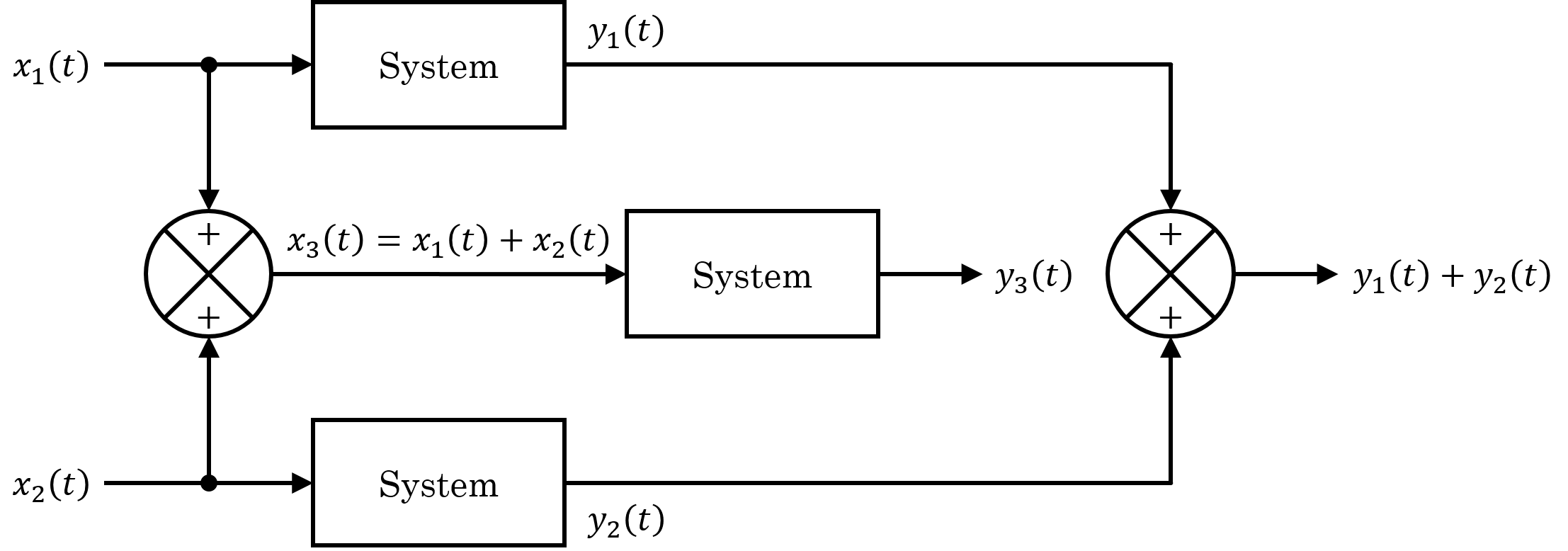
In systems theory, a linear system is a mathematical model of a system based on the use of a linear operator. Linear systems typically exhibit features and properties that are much simpler than the nonlinear case. As a mathematical abstraction or idealization, linear systems find important applications in automatic control theory, signal processing, and telecommunications. For example, the propagation medium for wireless communication systems can often be modeled by linear systems. Definition A general deterministic system can be described by an operator, that maps an input, as a function of to an output, a type of black box description. A system is linear if and only if it satisfies the superposition principle, or equivalently both the additivity and homogeneity properties, without restrictions (that is, for all inputs, all scaling constants and all time.) The superposition principle means that a linear combination of inputs to the system produces a linear combination ... [...More Info...] [...Related Items...] OR: [Wikipedia] [Google] [Baidu] |
Three-phase
Three-phase electric power (abbreviated 3φ) is a common type of alternating current used in electricity generation, Electric power transmission, transmission, and Electric power distribution, distribution. It is a type of polyphase system employing three wires (or four including an optional neutral return wire) and is the most common method used by electrical grids worldwide to transfer power. Three-phase electrical power was developed in the 1880s by multiple people. Three-phase power works by the voltage and currents being 120 degrees phase shift, out of phase on the three wires. As an AC system it allows the voltages to be easily stepped up using transformers to high voltage for transmission, and back down for distribution, giving high efficiency. A three-wire three-phase circuit is usually more economical than an equivalent two-wire Single-phase electric power, single-phase circuit at the same line to ground voltage because it uses less conductor material to transmit a giv ... [...More Info...] [...Related Items...] OR: [Wikipedia] [Google] [Baidu] |
Electrical Substation
A substation is a part of an electrical generation, transmission, and distribution system. Substations transform voltage from high to low, or the reverse, or perform any of several other important functions. Between the generating station and consumer, electric power may flow through several substations at different voltage levels. A substation may include transformers to change voltage levels between high transmission voltages and lower distribution voltages, or at the interconnection of two different transmission voltages. They are a common component of the infrastructure, for instance there are 55,000 substations in the United States. Substations may be owned and operated by an electrical utility, or may be owned by a large industrial or commercial customer. Generally substations are unattended, relying on SCADA for remote supervision and control. The word ''substation'' comes from the days before the distribution system became a grid. As central generation stations became ... [...More Info...] [...Related Items...] OR: [Wikipedia] [Google] [Baidu] |
One-line Diagram
In power engineering, a single-line diagram (SLD), also sometimes called one-line diagram, is a simplest symbolic representation of an electric power system. A single line in the diagram typically corresponds to more than one physical conductor: in a direct current system the line includes the supply and return paths, in a three-phase system the line represents all three phases (the conductors are both supply and return due to the nature of the alternating current circuits). The one-line diagram has its largest application in power flow studies. Electrical elements such as circuit breakers, transformers, capacitors, bus bars, and conductors are shown by standardized schematic symbols. Instead of representing each of three phases with a separate line or terminal, only one conductor is represented. It is a form of block diagram graphically depicting the paths for power flow between entities of the system. Elements on the diagram do not represent the physical size or location ... [...More Info...] [...Related Items...] OR: [Wikipedia] [Google] [Baidu] |
Ladder Logic
Ladder logic was originally a written method to document the design and construction of relay racks as used in manufacturing and process control. Each device in the relay rack would be represented by a symbol on the ladder diagram with connections between those devices shown. In addition, other items external to the relay rack such as pumps, heaters, and so forth would also be shown on the ladder diagram. Ladder logic has evolved into a programming language that represents a program by a graphical diagram based on the circuit diagrams of relay logic hardware. Ladder logic is used to develop software for programmable logic controllers (PLCs) used in industrial control applications. The name is based on the observation that programs in this language resemble ladders, with two vertical rails and a series of horizontal rungs between them. While ladder diagrams were once the only available notation for recording programmable controller programs, today other forms are standardized in ... [...More Info...] [...Related Items...] OR: [Wikipedia] [Google] [Baidu] |
Programmable Logic Controller
A programmable logic controller (PLC) or programmable controller is an industrial computer that has been ruggedized and adapted for the control of manufacturing processes, such as assembly lines, machines, robotic devices, or any activity that requires high reliability, ease of programming, and process fault diagnosis. Dick Morley is considered as the father of PLC as he had invented the first PLC, the Modicon 084, for General Motors in 1968. PLCs can range from small modular devices with tens of inputs and outputs (I/O), in a housing integral with the processor, to large rack-mounted modular devices with thousands of I/O, and which are often networked to other PLC and SCADA systems. They can be designed for many arrangements of digital and analog I/O, extended temperature ranges, immunity to electrical noise, and resistance to vibration and impact. Programs to control machine operation are typically stored in battery-backed-up or non-volatile memory. PLCs were first devel ... [...More Info...] [...Related Items...] OR: [Wikipedia] [Google] [Baidu] |


