|
Time Base Generator
A time base generator (also timebase or time base) is a special type of function generator, an electronic circuit that generates a varying voltage to produce a particular waveform. Time base generators produce very high frequency sawtooth waves specifically designed to deflect the beam of a cathode ray tube (CRT) smoothly across the face of the tube and then return it to its starting position. Time bases are used by radar systems to determine range to a target, by comparing the current location along the time base to the time of arrival of radio echoes. Analog television systems using CRTs had two time bases, one for deflecting the beam horizontally in a rapid movement, and another pulling it down the screen 60 times per second. Oscilloscopes often have several time bases, but these may be more flexible function generators able to produce many waveforms as well as a simple time base. Description A cathode ray tube (CRT) consists of three primary parts, the electron gun that provide ... [...More Info...] [...Related Items...] OR: [Wikipedia] [Google] [Baidu] |
Function Generator
In electrical engineering, a function generator is usually a piece of electronic test equipment or software used to generate different types of electrical waveforms over a wide range of frequencies. Some of the most common waveforms produced by the function generator are the sine wave, square wave, triangular wave and sawtooth shapes. These waveforms can be either repetitive or single-shot (which requires an internal or external trigger source).cnx.org - Using a Basic Function Generator 2005-08-21 Another feature included on many function generators is the ability to add a DC offset. |
Huff-duff
High-frequency direction finding, usually known by its abbreviation HF/DF or nickname huff-duff, is a type of radio direction finder (RDF) introduced in World War II. High frequency (HF) refers to a radio band that can effectively communicate over long distances; for example, between U-boats and their land-based headquarters. HF/DF was primarily used to catch enemy radios while they transmitted, although it was also used to locate friendly aircraft as a navigation aid. The basic technique remains in use as one of the fundamental disciplines of signals intelligence, although typically incorporated into a larger suite of radio systems and radars instead of being a stand-alone system. In earlier RDF systems, the operator mechanically rotated a loop antenna or solenoid and listened for peaks or nulls in the signal to determine the bearing to the transmitter. This took considerable time, on the order of a minute or more. Radio operators could avoid being located by keeping their messag ... [...More Info...] [...Related Items...] OR: [Wikipedia] [Google] [Baidu] |
Electronic Test Equipment
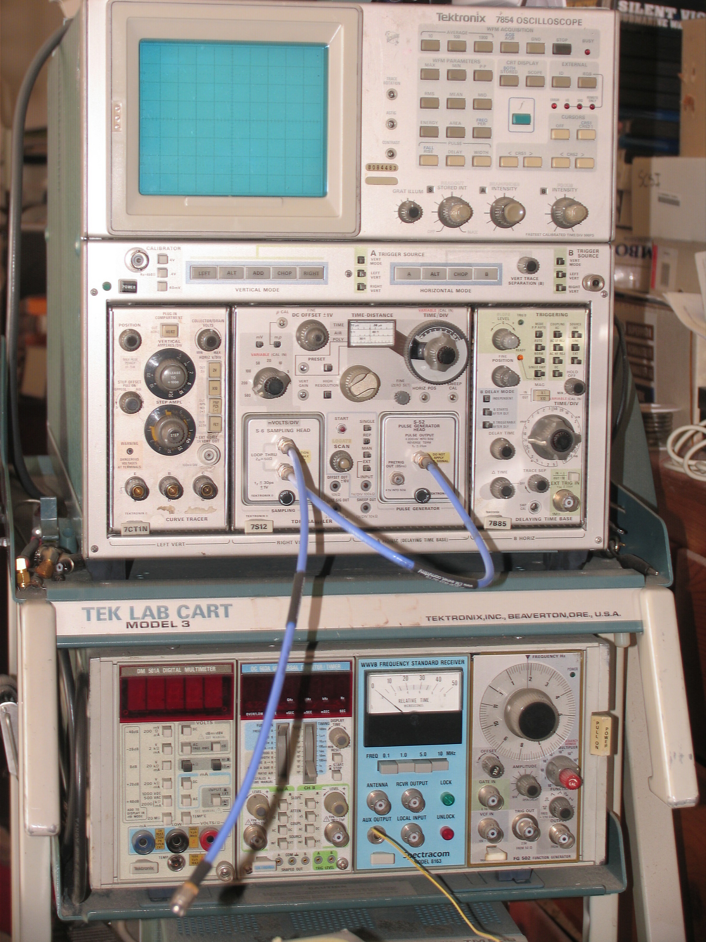
Electronic test equipment is used to create signals and capture responses from electronic devices under test (DUTs). In this way, the proper operation of the DUT can be proven or faults in the device can be traced. Use of electronic test equipment is essential to any serious work on electronics systems. Practical electronics engineering and assembly requires the use of many different kinds of electronic test equipment ranging from the very simple and inexpensive (such as a test light consisting of just a light bulb and a test lead) to extremely complex and sophisticated such as automatic test equipment (ATE). ATE often includes many of these instruments in real and simulated forms. Generally, more advanced test gear is necessary when developing circuits and systems than is needed when doing production testing or when troubleshooting existing production units in the field. Types of test equipment Basic equipment The following items are used for basic measurement of voltages, c ... [...More Info...] [...Related Items...] OR: [Wikipedia] [Google] [Baidu] |
Vertical Blanking Interval
In a raster scan display, the vertical blanking interval (VBI), also known as the vertical interval or VBLANK, is the time between the end of the final visible line of a frame or field and the beginning of the first visible line of the next frame or field. It is present in analog television, VGA, DVI and other signals. Here the term field is used in interlaced video, and the term frame is used in progressive video and there can be a VBI after each frame or field. In interlaced video a frame is made up of 2 fields. Sometimes in interlaced video a field is called a frame which can lead to confusion. In raster cathode-ray tube (CRT) displays, the blank level is usually supplied during this period to avoid painting the retrace line—see raster scan for details; signal sources such as television broadcasts do not supply image information during the blanking period. Digital displays usually will not display incoming data stream during the blanking interval even if present. The ... [...More Info...] [...Related Items...] OR: [Wikipedia] [Google] [Baidu] |
NTSC
NTSC (from National Television System Committee) is the first American standard for analog television, published and adopted in 1941. In 1961, it was assigned the designation System M. It is also known as EIA standard 170. In 1953, a second NTSC standard was adopted, which allowed for color television broadcast compatible with the existing stock of black-and-white receivers. It is one of three major color formats for analog television, the others being PAL and SECAM. ''NTSC color'' is usually associated with the System M; this combination is sometimes called NTSC II. The only other broadcast television system to use NTSC color was the System J. Brazil used System M with PAL color. Vietnam, Cambodia and Laos used System M with SECAM color – Vietnam later started using PAL in the early 1990s. The NTSC/System M standard was used in most of the Americas (except Argentina, Brazil, Paraguay, and Uruguay), Myanmar, South Korea, Taiwan, Philippines, Japan, and some Pacific Isl ... [...More Info...] [...Related Items...] OR: [Wikipedia] [Google] [Baidu] |
Chain Home
Chain Home, or CH for short, was the codename for the ring of coastal early warning radar stations built by the Royal Air Force (RAF) before and during the Second World War to detect and track aircraft. Initially known as RDF, and given the official name Air Ministry Experimental Station Type 1 ( AMES Type 1) in 1940, the radar units were also known as Chain Home for most of their life. Chain Home was the first early warning radar network in the world and the first military radar system to reach operational status. Its effect on the war made it one of the most powerful systems of what became known as the "Wizard War". In late 1934, the Tizard Committee asked radio expert Robert Watson-Watt to comment on the repeated claims of radio death rays and reports suggesting Germany had built some sort of radio weapon. His assistant, Arnold Wilkins, demonstrated that a death ray was impossible but suggested radio could be used for long-range detection. In February 1935, a successful d ... [...More Info...] [...Related Items...] OR: [Wikipedia] [Google] [Baidu] |
Early Warning Radar
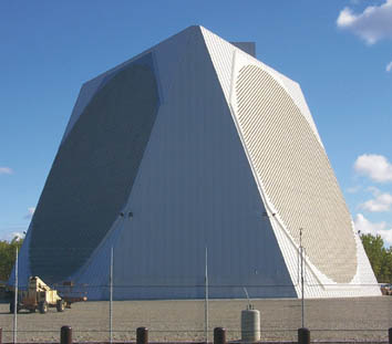
An early-warning radar is any radar system used primarily for the long-range detection of its targets, i.e., allowing defences to be alerted as ''early'' as possible before the intruder reaches its target, giving the air defences the maximum time in which to operate. This contrasts with systems used primarily for tracking or gun laying, which tend to offer shorter ranges but offer much higher accuracy. EW radars tend to share a number of design features that improve their performance in the role. For instance, EW radar typically operates at lower frequencies, and thus longer wavelengths, than other types. This greatly reduces their interaction with rain and snow in the air, and therefore improves their performance in the long-range role where their coverage area will often include precipitation. This also has the side-effect of lowering their optical resolution, but this is not important in this role. Likewise, EW radars often use much lower pulse repetition frequency to maximiz ... [...More Info...] [...Related Items...] OR: [Wikipedia] [Google] [Baidu] |
Radar Display
A radar display is an electronic device that presents radar data to the operator. The radar system transmits pulses or continuous waves of electromagnetic radiation, a small portion of which backscatter off targets (intended or otherwise) and return to the radar system. The receiver converts all received electromagnetic radiation into a continuous electronic analog signal of varying (or oscillating) voltage that can be converted then to a screen display. Modern systems typically use some sort of raster graphics, raster scan display to produce a map-like image. Early in radar development, however, numerous circumstances made such displays difficult to produce. People developed several different display types. Oscilloscopes Early radar displays used adapted oscilloscopes with various inputs. An oscilloscope generally receives three ''channels'' of varying (or oscillating) voltage as input and displays this information on a cathode ray tube. The oscilloscope amplifies the input vo ... [...More Info...] [...Related Items...] OR: [Wikipedia] [Google] [Baidu] |
Speed Of Light
The speed of light in vacuum, commonly denoted , is a universal physical constant exactly equal to ). It is exact because, by international agreement, a metre is defined as the length of the path travelled by light in vacuum during a time interval of second. The speed of light is invariant (physics), the same for all observers, no matter their relative velocity. It is the upper limit for the speed at which Information#Physics_and_determinacy, information, matter, or energy can travel through Space#Relativity, space. All forms of electromagnetic radiation, including visible light, travel at the speed of light. For many practical purposes, light and other electromagnetic waves will appear to propagate instantaneously, but for long distances and sensitive measurements, their finite speed has noticeable effects. Much starlight viewed on Earth is from the distant past, allowing humans to study the history of the universe by viewing distant objects. When Data communication, comm ... [...More Info...] [...Related Items...] OR: [Wikipedia] [Google] [Baidu] |
Frequency Modulation
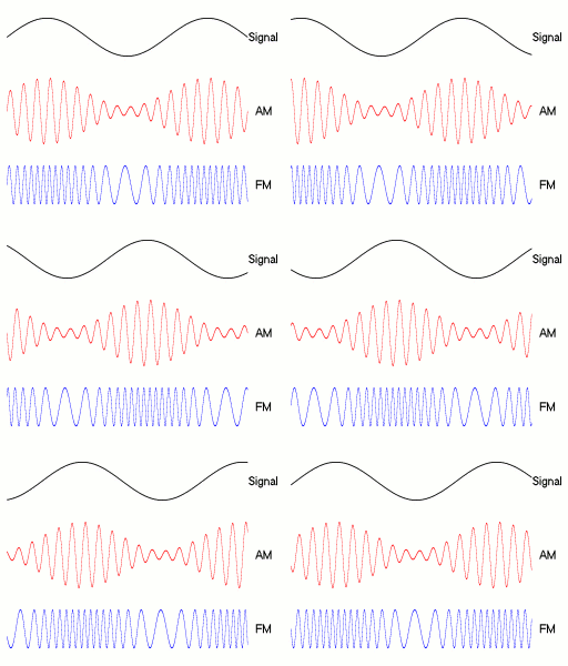
Frequency modulation (FM) is a signal modulation technique used in electronic communication, originally for transmitting messages with a radio wave. In frequency modulation a carrier wave is varied in its instantaneous frequency in proportion to a property, primarily the instantaneous amplitude, of a message signal, such as an audio signal. The technology is used in telecommunications, radio broadcasting, signal processing, and Run-length limited#FM: .280.2C1.29 RLL, computing. In Analog signal, analog frequency modulation, such as radio broadcasting of voice and music, the instantaneous frequency deviation, i.e. the difference between the frequency of the carrier and its center frequency, has a functional relation to the modulating signal amplitude. Digital data can be encoded and transmitted with a type of frequency modulation known as frequency-shift keying (FSK), in which the instantaneous frequency of the carrier is shifted among a set of frequencies. The frequencies m ... [...More Info...] [...Related Items...] OR: [Wikipedia] [Google] [Baidu] |
Amplitude Modulation
Amplitude modulation (AM) is a signal modulation technique used in electronic communication, most commonly for transmitting messages with a radio wave. In amplitude modulation, the instantaneous amplitude of the wave is varied in proportion to that of the message signal, such as an audio signal. This technique contrasts with angle modulation, in which either the frequency of the carrier wave is varied, as in frequency modulation, or its Phase (waves), phase, as in phase modulation. AM was the earliest modulation method used for transmitting audio in radio broadcasting. It was developed during the first quarter of the 20th century beginning with Roberto Landell de Moura and Reginald Fessenden's radiotelephone experiments in 1900. This original form of AM is sometimes called double-sideband amplitude modulation (DSBAM), because the standard method produces sidebands on either side of the carrier frequency. Single-sideband modulation uses bandpass filters to eliminate one of the ... [...More Info...] [...Related Items...] OR: [Wikipedia] [Google] [Baidu] |
Carrier Signal
In telecommunications, a carrier wave, carrier signal, or just carrier, is a periodic waveform (usually sinusoidal) that conveys information through a process called ''modulation''. One or more of the wave's properties, such as amplitude or frequency, are modified by an information bearing signal, called the ''message signal'' or ''modulation signal''. The carrier frequency is usually much higher than the message signal frequency; this is because it is usually impractical to transmit signals with low frequencies over long distances (due to attenuation). The purpose of the carrier is usually either to transmit the information through space as an electromagnetic wave (as in radio communication), or to allow several carriers at different frequencies to share a common physical transmission medium by frequency division multiplexing (as in a cable television system). The term originated in radio communication, where the carrier wave creates the waves which carry the information (modul ... [...More Info...] [...Related Items...] OR: [Wikipedia] [Google] [Baidu] |


