|
RF Switch Matrix
An RF switch matrix is an array of RF switches arranged to route radio frequency (RF) signals between multiple inputs and multiple outputs. Applications requiring RF matrices include ground systems, test equipment, and communication systems. An RF matrix is used in test systems, in both design verification and manufacturing test, to route high frequency signals between the device under test (DUT) and the test and measurement equipment. In addition to signal routing, the RF/Microwave Switch Matrix may also contain signal conditioning components including passive signal conditioning devices, such as attenuators, filters, and directional couplers, as well as active signal conditioning, such as amplification and frequency converters. Since the signal routing and signal conditioning needs of a test system differ from design to design, RF/Microwave Switch Matrices may be custom designed by the test system engineer or by a hired contractor for each new test system. The Switch Matrix is ... [...More Info...] [...Related Items...] OR: [Wikipedia] [Google] [Baidu] |
RF Switch
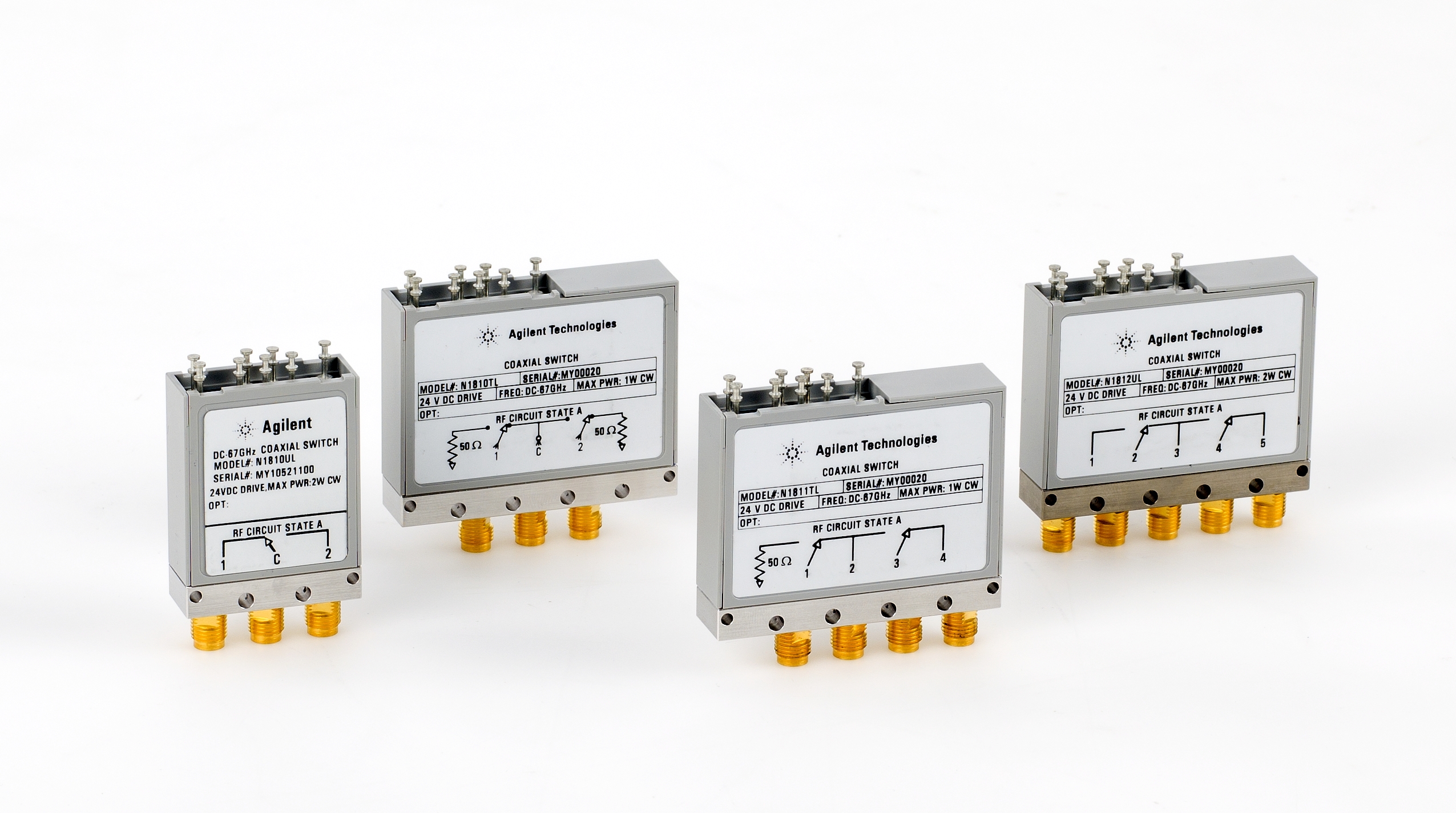
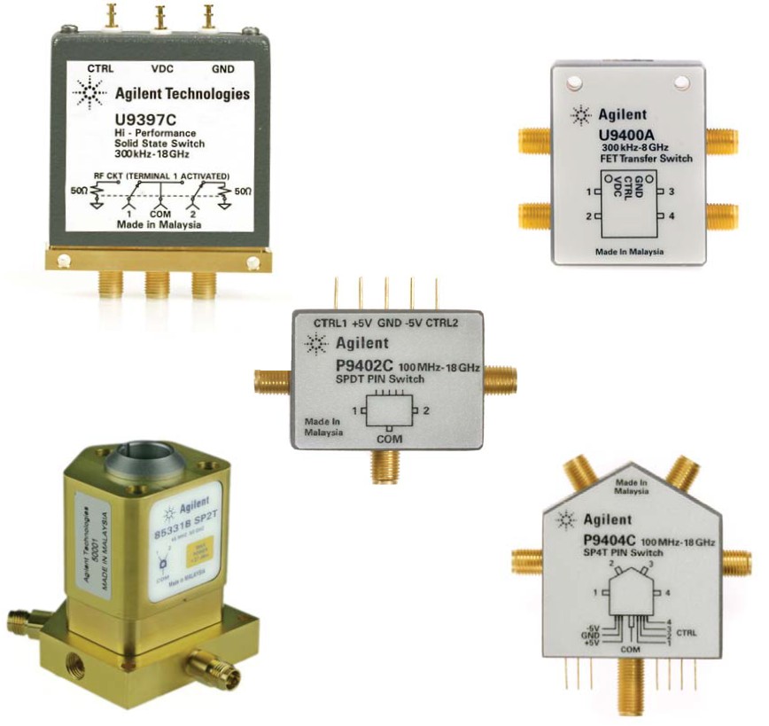
An RF switch or microwave switch is a device to route high frequency signals through transmission paths. RF (radio frequency) and microwave switches are used extensively in microwave test systems for signal routing between instruments and Device under test, devices under test (DUT). Incorporating a switch into a switch matrix system enables you to route signals from multiple instruments to single or multiple DUTs. This allows multiple tests to be performed with the same setup, eliminating the need for frequent connects and disconnects. The entire testing process can be automated, increasing the throughput in high-volume production environments. Like other switch, electrical switches, RF and microwave switches provide different configurations for many different applications. Below is a list of typical switch configurations and usage: * Single pole, double throw (SPDT or 1:2) switches route signals from one input to two output paths. * Multiport switches or single pole, multiple thro ... [...More Info...] [...Related Items...] OR: [Wikipedia] [Google] [Baidu] |
Microwave Switch
Microwave is a form of electromagnetic radiation with wavelengths shorter than other radio waves but longer than infrared waves. Its wavelength ranges from about one meter to one millimeter, corresponding to frequencies between 300 MHz and 300 GHz, broadly construed. A more common definition in radio-frequency engineering is the range between 1 and 100 GHz (wavelengths between 30 cm and 3 mm), or between 1 and 3000 GHz (30 cm and 0.1 mm). In all cases, microwaves include the entire super high frequency (SHF) band (3 to 30 GHz, or 10 to 1 cm) at minimum. The boundaries between far infrared, terahertz radiation, microwaves, and ultra-high-frequency (UHF) are fairly arbitrary and differ between different fields of study. The prefix ' in ''microwave'' indicates that microwaves are small (having shorter wavelengths), compared to the radio waves used in prior radio technology. Frequencies in the microwave range are often referred ... [...More Info...] [...Related Items...] OR: [Wikipedia] [Google] [Baidu] |
Cable Television Headend
A cable television headend is a master facility for receiving television signals for processing and distribution over a cable television system. A headend facility may be staffed or unstaffed and is typically surrounded by some type of security fencing. The building is typically sturdy and purpose-built to provide security, cooling, and easy access for the electronic equipment used to receive and re-transmit video over the local cable infrastructure. One can also find head ends in power-line communication (PLC) substations and Internet communications networks. Reception Nearly all cable TV systems carry subscription content that is relayed from a satellite in geosynchronous orbit. Encrypted to prevent unauthorized use, this content is uplinked from one or more earth stations operated by various content delivery companies. The content is then analog or digitally modulated and transmitted through the cable network (the OSP or "OutSide Plant") to subscriber homes by means of co ... [...More Info...] [...Related Items...] OR: [Wikipedia] [Google] [Baidu] |
Jitter
In electronics and telecommunications, jitter is the deviation from true periodicity of a presumably periodic signal, often in relation to a reference clock signal. In clock recovery applications it is called timing jitter. Jitter is a significant, and usually undesired, factor in the design of almost all communications links. Jitter can be quantified in the same terms as all time-varying signals, e.g., root mean square (RMS), or peak-to-peak displacement. Also, like other time-varying signals, jitter can be expressed in terms of spectral density. Jitter period is the interval between two times of maximum effect (or minimum effect) of a signal characteristic that varies regularly with time. Jitter frequency, the more commonly quoted figure, is its inverse. ITU-T G.810 classifies deviation lower frequencies below 10 Hz as ''wander'' and higher frequencies at or above 10 Hz as ''jitter''. Jitter may be caused by electromagnetic interference and crosstalk with ca ... [...More Info...] [...Related Items...] OR: [Wikipedia] [Google] [Baidu] |
Coax Cable
Coaxial cable, or coax (pronounced ), is a type of electrical cable consisting of an inner conductor surrounded by a concentric conducting shield, with the two separated by a dielectric ( insulating material); many coaxial cables also have a protective outer sheath or jacket. The term ''coaxial'' refers to the inner conductor and the outer shield sharing a geometric axis. Coaxial cable is a type of transmission line, used to carry high-frequency electrical signals with low losses. It is used in such applications as telephone trunk lines, broadband internet networking cables, high-speed computer data buses, cable television signals, and connecting radio transmitters and receivers to their antennas. It differs from other shielded cables because the dimensions of the cable and connectors are controlled to give a precise, constant conductor spacing, which is needed for it to function efficiently as a transmission line. Coaxial cable was used in the first (1858) and follow ... [...More Info...] [...Related Items...] OR: [Wikipedia] [Google] [Baidu] |
Spectrum Analyzer
A spectrum analyzer measures the magnitude of an input signal versus frequency within the full frequency range of the instrument. The primary use is to measure the power of the spectrum of known and unknown signals. The input signal that most common spectrum analyzers measure is electrical; however, spectral compositions of other signals, such as acoustic pressure waves and optical light waves, can be considered through the use of an appropriate transducer. Spectrum analyzers for other types of signals also exist, such as optical spectrum analyzers which use direct optical techniques such as a monochromator to make measurements. By analyzing the spectra of electrical signals, dominant frequency, power, distortion, harmonics, bandwidth, and other spectral components of a signal can be observed that are not easily detectable in time domain waveforms. These parameters are useful in the characterization of electronic devices, such as wireless transmitters. The display of a spec ... [...More Info...] [...Related Items...] OR: [Wikipedia] [Google] [Baidu] |
VSWR
In Radio-frequency engineering, radio engineering and telecommunications, standing wave ratio (SWR) is a measure of impedance matching of Electrical load, loads to the characteristic impedance of a transmission line or waveguide. Impedance mismatches result in standing waves along the transmission line, and SWR is defined as the ratio of the partial standing wave's amplitude at an antinode (maximum) to the amplitude at a node (physics), node (minimum) along the line. Voltage standing wave ratio (VSWR) (pronounced "vizwar" ) is the ratio of maximum to minimum voltage on a transmission line . For example, a VSWR of 1.2 means a peak voltage 1.2 times the minimum voltage along that line, if the line is at least one half wavelength long. A SWR can be also defined as the ratio of the maximum amplitude to minimum amplitude of the transmission line's Current (electricity), currents, electric field strength, or the magnetic field strength. Neglecting transmission line loss, these rati ... [...More Info...] [...Related Items...] OR: [Wikipedia] [Google] [Baidu] |
PIN Diode
A PIN diode is a diode with a wide, undoped intrinsic semiconductor region between a p-type semiconductor and an n-type semiconductor region. The p-type and n-type regions are typically heavily doping (semiconductor), doped because they are used for ohmic contacts. The wide Intrinsic semiconductor, intrinsic region is in contrast to an ordinary p–n diode. The wide intrinsic region makes the PIN diode an inferior rectifier (one typical function of a diode), but it makes it suitable for attenuators, fast switches, photodetectors, and high-voltage power electronics applications. The PIN photodiode was invented by Jun-Ichi Nishizawa and his colleagues in 1950. It is a semiconductor device. Operation A PIN diode operates under what is known as high-level injection. In other words, the intrinsic "i" region is flooded with charge carriers from the "p" and "n" regions. Its function can be likened to filling up a water bucket with a hole on the side. Once the water reaches the hole ... [...More Info...] [...Related Items...] OR: [Wikipedia] [Google] [Baidu] |
Switch
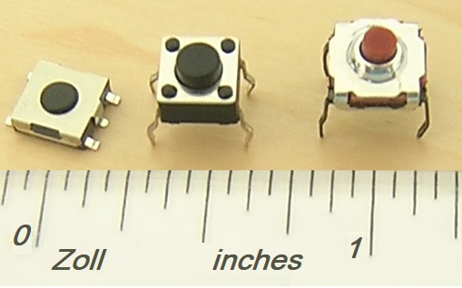
In electrical engineering, a switch is an electrical component that can disconnect or connect the conducting path in an electrical circuit, interrupting the electric current or diverting it from one conductor to another. The most common type of switch is an electromechanical device consisting of one or more sets of movable electrical contacts connected to external circuits. When a pair of contacts is touching current can pass between them, while when the contacts are separated no current can flow. Switches are made in many different configurations; they may have multiple sets of contacts controlled by the same knob or actuator, and the contacts may operate simultaneously, sequentially, or alternately. A switch may be operated manually, for example, a light switch or a keyboard button, or may function as a sensing element to sense the position of a machine part, liquid level, pressure, or temperature, such as a thermostat. Many specialized forms exist, such as the toggle swit ... [...More Info...] [...Related Items...] OR: [Wikipedia] [Google] [Baidu] |
Electromechanical
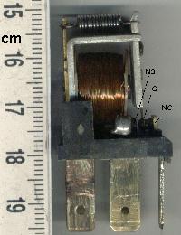
Electromechanics combine processes and procedures drawn from electrical engineering and mechanical engineering. Electromechanics focus on the interaction of electrical and mechanical systems as a whole and how the two systems interact with each other. This process is especially prominent in systems such as those of DC or AC rotating electrical machines which can be designed and operated to generate power from a mechanical process ( generator) or used to power a mechanical effect ( motor). Electrical engineering in this context also encompasses electronics engineering. Electromechanical devices are ones which have both electrical and mechanical processes. Strictly speaking, a manually operated switch is an electromechanical component due to the mechanical movement causing an electrical output. Though this is true, the term is usually understood to refer to devices which involve an electrical signal to create mechanical movement, or vice versa mechanical movement to create an ele ... [...More Info...] [...Related Items...] OR: [Wikipedia] [Google] [Baidu] |
Electronic Switch
In electronics, an electronic switch is a switch controlled by an Passivity (engineering), active electronic component or device. Without using moving parts, they are called solid state switches, which distinguishes them from mechanical switches. Electronic switches are considered Binary number, binary devices because they dramatically change the Electrical resistivity and conductivity, conductivity of a path in electrical circuit between two extremes when switching between their two states of ''on'' and ''off''. History Many people use metonymy to call a variety of devices that conceptually connect or disconnect signals and communication paths between electrical devices as "switches", analogous to the way mechanical switches connect and disconnect paths for electrons to flow between two conductors. The traditional relay is an electromechanical switch that uses an electromagnet controlled by a current to operate a mechanical switching mechanism. Other operating principles ar ... [...More Info...] [...Related Items...] OR: [Wikipedia] [Google] [Baidu] |
Coaxial
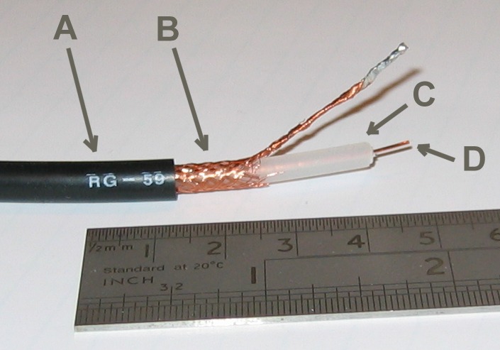
In geometry, coaxial means that several three-dimensional linear or planar forms share a common axis. The two-dimensional analog is ''concentric''. Common examples: A coaxial cable has a wire conductor in the centre (D), a circumferential outer conductor (B), and an insulating medium called the dielectric (C) separating these two conductors. The outer conductor is usually sheathed in a protective PVC outer jacket (A). All these have a common axis. The dimension and material of the conductors and insulation determine the cable's characteristic impedance and attenuation at various frequencies. Coaxial rotors are a three-dimensional planar structure: a pair of helicopter rotors (wings) mounted one above the other on concentric shafts, with the same axis of rotation (but turning in opposite directions). In loudspeaker design, coaxial speakers are a loudspeaker system in which the individual drivers are mounted close to one another on the same axis, and thus radiate sound along t ... [...More Info...] [...Related Items...] OR: [Wikipedia] [Google] [Baidu] |
