|
List Of STEP (ISO 10303) Parts
An incomplete list of parts making up STEP (ISO 10303): Descriptions methods * Part 1 - ''Overview and fundamental principles'' (1994). Unfortunately outdated, not covering the role of AICs and modules. * Part 11 - ''EXPRESS language reference manual'' * Part 12 - ''EXPRESS -I language reference manual (withdrawn)'' * Part 14 - ''EXPRESS -X language reference manual'' Implementation methods * Part 15 - ''SysML XMI to XSD transformation'' * Part 21 - STEP-File ''Clear text encoding of the exchange structure'' * Part 22 - SDAI ''Standard data access interface specification'' * Part 23 - ''C++ language binding of the standard data access interface'' * Part 24 - ''C language binding of the standard data access interface'' * Part 25 - ''EXPRESS to OMG XMI binding'' * Part 26 - ''Binary representation of EXPRESS-driven data'' using HDF5 * Part 27 - ''Java TM programming language binding to the standard data access interface with Internet/Intranet extensions'' * Part 28 - STEP-XML ''XM ... [...More Info...] [...Related Items...] OR: [Wikipedia] [Google] [Baidu] [Amazon] |
ISO 10303
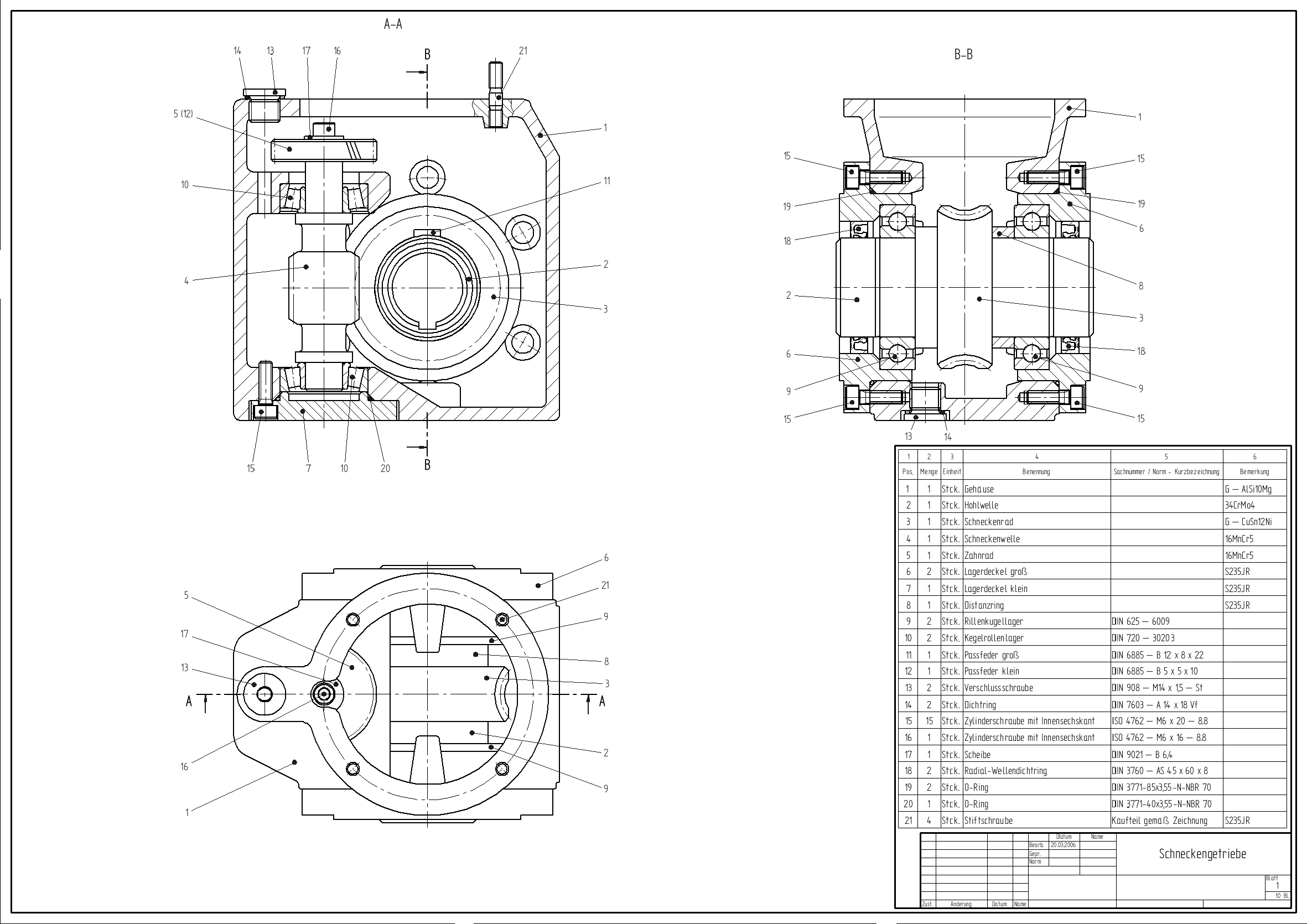
ISO 10303 (Automation systems and integration — Product data representation and exchange)ISO 10303-1:1994 Industrial automation systems and integration -- Product data representation and exchange -- Part 1: Overview and fundamental principles is a family of ISO standards for computer-interpretable representation (description) and exchange of product manufacturing information (PMI). It aims to provide interoperability between various computer-aided design (CAD) software, assist with automation in computer-aided manufacturing (CAM), and allows long-term archival of 3D, CAD and PDM data. It is known informally as "STEP", which stands for "''Standard for the Exchange of Product model data''". Due to a large scope ISO 10303 is subdivided into approximately 700 underlying standards total. The standard includes Parts 11-18 and Part 21 that describe EXPRESS data schema definition language and STEP-file (also STEP-XML) used for textual representation of PMI data codified by the ... [...More Info...] [...Related Items...] OR: [Wikipedia] [Google] [Baidu] [Amazon] |
Java 2D
Java 2D is an API for drawing two-dimensional graphics using the Java programming language. Every Java 2D drawing operation can ultimately be treated as ''filling'' a ''shape'' using a ''paint'' and ''compositing'' the result onto the screen.The Java 2D is a set of classes for advanced 2D graphics and imaging. It encompasses line art, text, and images in a single comprehensive model. The API provides extensive support for image compositing and alpha channel images, a set of classes to provide accurate color space definition and conversion, and a rich set of display-oriented imaging operators. Organization The Java 2D API and its documentation are available for download as a part of JDK 6. Java 2D API classes are organised into the following packages in JDK 6: *' The main package for the Java Abstract Window Toolkit. *' The Java standard library of two dimensional geometric shapes such as lines, ellipses, and quadrilaterals. *' The library for manipulating glyphs in Java. *' The l ... [...More Info...] [...Related Items...] OR: [Wikipedia] [Google] [Baidu] [Amazon] |
CAD File Formats
Computer-aided design (CAD) is the use of computers (or ) to aid in the creation, modification, analysis, or optimization of a design. This software is used to increase the productivity of the designer, improve the quality of design, improve communications through documentation, and to create a database for manufacturing. Designs made through CAD software help protect products and inventions when used in patent applications. CAD output is often in the form of electronic files for print, machining, or other manufacturing operations. The terms computer-aided drafting (CAD) and computer-aided design and drafting (CADD) are also used. Its use in designing electronic systems is known as ''electronic design automation'' (''EDA''). In mechanical design it is known as ''mechanical design automation'' (''MDA''), which includes the process of creating a technical drawing with the use of computer software. CAD software for mechanical design uses either Vector graphics, vector-based graph ... [...More Info...] [...Related Items...] OR: [Wikipedia] [Google] [Baidu] [Amazon] |
Computer-aided Design Software
Automation describes a wide range of technologies that reduce human intervention in processes, mainly by predetermining decision criteria, subprocess relationships, and related actions, as well as embodying those predeterminations in machines. Automation has been achieved by various means including mechanical, hydraulic, pneumatic, electrical, electronic devices, and computers, usually in combination. Complicated systems, such as modern factories, airplanes, and ships typically use combinations of all of these techniques. The benefit of automation includes labor savings, reducing waste, savings in electricity costs, savings in material costs, and improvements to quality, accuracy, and precision. Automation includes the use of various equipment and control systems such as machinery, processes in factories, boilers, and heat-treating ovens, switching on telephone networks, steering, stabilization of ships, aircraft and other applications and vehicles with reduced huma ... [...More Info...] [...Related Items...] OR: [Wikipedia] [Google] [Baidu] [Amazon] |
Non-manifold Model
In solid modeling and computer-aided design, boundary representation (often abbreviated B-rep or BREP) is a method for representing a 3D shape by defining the limits of its volume. A solid is represented as a collection of connected surface elements, which define the boundary between interior and exterior points. Overview A boundary representation of a model comprises topological components (faces, edges and vertices) and the connections between them, along with geometric definitions for those components (surfaces, curves and points, respectively). A face is a bounded portion of a surface; an edge is a bounded piece of a curve and a vertex lies at a point. Other elements are the ''shell'' (a set of connected faces), the ''loop'' (a circuit of edges bounding a face) and ''loop-edge links'' (also known as ''winged edge links'' or ''half-edges'') which are used to create the edge circuits. Compared to constructive solid geometry Compared to the constructive solid geometry ... [...More Info...] [...Related Items...] OR: [Wikipedia] [Google] [Baidu] [Amazon] |
STEP-NC
STEP-NC is a machine tool control language that extends the ISO 10303 STEP standards with the machining model in ISO 14649, adding geometric dimension and tolerance data for inspection, and the STEP PDM model for integration into the wider enterprise. The combined result has been standardized as ISO 10303-238 (also known as AP238). STEP-NC was designed to replace ISO 6983/RS274D G-codes with a modern, associative communications protocol that connects computer numerical controlled (CNC) process data to a product description of the part being machined. A STEP-NC program can use the full range of geometric constructs from the STEP standard to communicate device-independent toolpaths to the CNC. It can provide CAM operational descriptions and STEP CAD geometry to the CNC so workpieces, stock, fixtures and cutting tool shapes can be visualized and analyzed in the context of the toolpaths. STEP GD&T information can also be added to enable quality measurement on the control, and C ... [...More Info...] [...Related Items...] OR: [Wikipedia] [Google] [Baidu] [Amazon] |
Geometric Dimensioning And Tolerancing
Geometric dimensioning and tolerancing (GD&T) is a system for defining and communicating engineering tolerances via a Symbolic language (engineering), symbolic language on engineering drawings and computer-generated Solid modeling, 3D models that describes a physical object's nominal geometry and the permissible variation thereof. GD&T is used to define the nominal (theoretically perfect) geometry of parts and assemblies, the allowable variation in size, form, orientation, and location of individual features, and how features may vary in relation to one another such that a component is considered satisfactory for its intended use. Dimensional specifications define the nominal, as-modeled or as-intended geometry, while tolerance specifications define the allowable physical variation of individual features of a part or assembly. There are several standards available worldwide that describe the symbols and define the rules used in GD&T. One such standard is American Society of Mecha ... [...More Info...] [...Related Items...] OR: [Wikipedia] [Google] [Baidu] [Amazon] |
OpenGL
OpenGL (Open Graphics Library) is a Language-independent specification, cross-language, cross-platform application programming interface (API) for rendering 2D computer graphics, 2D and 3D computer graphics, 3D vector graphics. The API is typically used to interact with a graphics processing unit (GPU), to achieve Hardware acceleration, hardware-accelerated Rendering (computer graphics), rendering. Silicon Graphics, Inc. (SGI) began developing OpenGL in 1991 and released it on June 30, 1992. It is used for a variety of applications, including computer-aided design (CAD), video games, scientific visualization, virtual reality, and Flight simulator, flight simulation. Since 2006, OpenGL has been managed by the Non-profit organization, non-profit technology consortium Khronos Group. Design The OpenGL specification describes an abstract application programming interface, application programming interface (API) for drawing 2D and 3D graphics. It is designed to be implemented mostly ... [...More Info...] [...Related Items...] OR: [Wikipedia] [Google] [Baidu] [Amazon] |
ISO 10303-11
The International Organization for Standardization (ISO ; ; ) is an independent, non-governmental, international standard development organization composed of representatives from the national standards organizations of member countries. Membership requirements are given in Article 3 of the ISO Statutes. ISO was founded on 23 February 1947, and () it has published over 25,000 international standards covering almost all aspects of technology and manufacturing. It has over 800 technical committees (TCs) and subcommittees (SCs) to take care of standards development. The organization develops and publishes international standards in technical and nontechnical fields, including everything from manufactured products and technology to food safety, transport, IT, agriculture, and healthcare. More specialized topics like electrical and electronic engineering are instead handled by the International Electrotechnical Commission.Editors of Encyclopedia Britannica. 3 June 2021.Internatio ... [...More Info...] [...Related Items...] OR: [Wikipedia] [Google] [Baidu] [Amazon] |
PHIGS
PHIGS (Programmer's Hierarchical Interactive Graphics System) is an application programming interface (API) standard for rendering 3D computer graphics, considered to be the 3D graphics standard for the 1980s through the early 1990s. Subsequently, a combination of features and power led to the rise of OpenGL, which became the most popular professional 3D API of the mid to late 1990s. Large vendors typically offered versions of PHIGS for their platforms, including DEC PHIGS, IBM's graPHIGS and Sun's SunPHIGS. It could also be used within the X Window System, supported via PEX. PEX consisted of an extension to X, adding commands that would be forwarded from the X server to the PEX system for rendering. Workstations were placed in windows typically, but could also be forwarded to take over the whole screen, or to various printer-output devices. PHIGS was designed in the 1980s, inheriting many of its ideas from the 2D Graphical Kernel System (GKS) of the late 1970s, and became a stan ... [...More Info...] [...Related Items...] OR: [Wikipedia] [Google] [Baidu] [Amazon] |
Graphical Kernel System
The Graphical Kernel System (GKS) is a 2D computer graphics system using vector graphics, introduced in 1977. It was suitable for making line and bar charts and similar tasks. A key concept was cross-system portability, based on an underlying coordinate system that could be represented on almost any hardware. GKS is best known as the basis for the graphics in the GEM GUI system used on the Atari ST and as part of Ventura Publisher. A draft international standard was circulated for review in September 1983. Final ratification of the standard was achieved in 1985, making it the first ISO graphics standard. A 3D system modelled on GKS was introduced as PHIGS, which saw some use in the 1980s and early 1990s. Overview GKS provides a set of drawing features for two-dimensional vector graphics suitable for charting and similar duties. The calls are designed to be portable across different programming languages, graphics devices and hardware, so that applications written to use GK ... [...More Info...] [...Related Items...] OR: [Wikipedia] [Google] [Baidu] [Amazon] |


