|
Dynatron Oscillator
In electronics, the dynatron oscillator, invented in 1918 by Albert Hull at General Electric, is an obsolete vacuum tube electronic oscillator circuit which uses a negative resistance characteristic in early tetrode vacuum tubes, caused by a process called secondary emission. on Peter Millet'Tubebookswebsite It was the first negative resistance vacuum tube oscillator. The dynatron oscillator circuit was used to a limited extent as beat frequency oscillators (BFOs), and local oscillators in vacuum tube radio receivers as well as in scientific and test equipment from the 1920s to the 1940s but became obsolete around World War 2 due to the variability of secondary emission in tubes. Negative transconductance oscillators, such as the transitron oscillator invented by Cleto Brunetti in 1939, are similar negative resistance vacuum tube oscillator circuits which are based on negative transconductance (a fall in current through one grid electrode caused by an increase in voltage on a ... [...More Info...] [...Related Items...] OR: [Wikipedia] [Google] [Baidu] |
Signal Generator
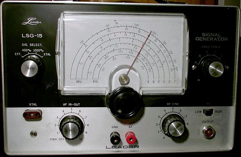
A signal generator is one of a class of electronic devices that generates electrical signals with set properties of amplitude, frequency, and wave shape. These generated signals are used as a stimulus for electronic measurements, typically used in designing, testing, troubleshooting, and repairing electronic or electroacoustic devices, though it often has artistic uses as well. There are many different types of signal generators with different purposes and applications and at varying levels of expense. These types include function generators, RF and microwave signal generators, pitch generators, arbitrary waveform generators, digital pattern generators, and frequency generators. In general, no device is suitable for all possible applications. A signal generator may be as simple as an oscillator with calibrated frequency and amplitude. More general-purpose signal generators allow control of all the characteristics of a signal. Modern general-purpose signal generators will have ... [...More Info...] [...Related Items...] OR: [Wikipedia] [Google] [Baidu] |
Inductor
An inductor, also called a coil, choke, or reactor, is a passive two-terminal electrical component that stores energy in a magnetic field when electric current flows through it. An inductor typically consists of an insulated wire wound into a coil. When the current flowing through the coil changes, the time-varying magnetic field induces an electromotive force (''emf'') (voltage) in the conductor, described by Faraday's law of induction. According to Lenz's law, the induced voltage has a polarity (direction) which opposes the change in current that created it. As a result, inductors oppose any changes in current through them. An inductor is characterized by its inductance, which is the ratio of the voltage to the rate of change of current. In the International System of Units (SI), the unit of inductance is the henry (H) named for 19th century American scientist Joseph Henry. In the measurement of magnetic circuits, it is equivalent to . Inductors have values that typically ra ... [...More Info...] [...Related Items...] OR: [Wikipedia] [Google] [Baidu] |
Dynatron Oscillator Circuit
Dynatron can refer to: * Dynatron oscillator, type of vacuum tube electronic oscillator circuit * Dynatron Radio Ltd Dynatron Radio Ltd was the trade name used by H.Hacker & Sons for their wireless products. The firm started trading in 1927 and operated independently until being bought by Ekco in 1955. The rights to the Dynatron name are currently held by Rober ..., British electronics company (1927-55) * Dynatron (music producer), Danish music producer {{disambig ... [...More Info...] [...Related Items...] OR: [Wikipedia] [Google] [Baidu] |
Armstrong Oscillator
The Armstrong oscillator (also known as the Meissner oscillator) is an electronic oscillator circuit which uses an inductor and capacitor to generate an oscillation. It is the earliest oscillator circuit, invented by US engineer Edwin Armstrong in 1912 and independently by Austrian engineer Alexander Meissner in 1913, and was used in the first vacuum tube radio transmitters. It is sometimes called a tickler oscillator because its distinguishing feature is that the feedback signal needed to produce oscillations is magnetically coupled into the tank inductor in the input circuit by a "tickler coil" ''(L2, right)'' in the output circuit. Assuming the coupling is weak but sufficient to sustain oscillation, the oscillation frequency ''f'' is determined primarily by the LC circuit (tank circuit L1 and C in the figure on the right) and is approximately given by :f = \frac \, This circuit was widely used in the regenerative radio receiver, popular until the 1940s. In that application ... [...More Info...] [...Related Items...] OR: [Wikipedia] [Google] [Baidu] |
Hartley Oscillator
The Hartley oscillator is an electronic oscillator circuit in which the oscillation frequency is determined by a tuned circuit consisting of capacitors and inductors, that is, an LC oscillator. The circuit was invented in 1915 by American engineer Ralph Hartley. The distinguishing feature of the Hartley oscillator is that the tuned circuit consists of a single capacitor in parallel with two inductors in series (or a single tapped inductor), and the feedback signal needed for oscillation is taken from the center connection of the two inductors. History The Hartley oscillator was invented by Hartley while he was working for the Research Laboratory of the Western Electric Company . Hartley invented and patented the design in 1915 while overseeing Bell System's transatlantic radiotelephone tests; it was awarded patent number 1,356,763 on October 26, 1920. Note that the basic schematic shown below labeled "Common-drain Hartley circuit" is essentially the same as in the patent dra ... [...More Info...] [...Related Items...] OR: [Wikipedia] [Google] [Baidu] |
Capacitance
Capacitance is the capability of a material object or device to store electric charge. It is measured by the change in charge in response to a difference in electric potential, expressed as the ratio of those quantities. Commonly recognized are two closely related notions of capacitance: ''self capacitance'' and ''mutual capacitance''. An object that can be electrically charged exhibits self capacitance, for which the electric potential is measured between the object and ground. Mutual capacitance is measured between two components, and is particularly important in the operations of the capacitor, a device designed for this purpose as an elementary linear electronic component. Capacitance is a function only of the geometry of the design of the capacitor, e.g., the opposing surface area of the plates and the distance between them, and the permittivity of the dielectric material between the plates. For many dielectric materials, the permittivity and thus the capacitance, is in ... [...More Info...] [...Related Items...] OR: [Wikipedia] [Google] [Baidu] |
Inductance
Inductance is the tendency of an electrical conductor to oppose a change in the electric current flowing through it. The flow of electric current creates a magnetic field around the conductor. The field strength depends on the magnitude of the current, and follows any changes in current. From Faraday's law of induction, any change in magnetic field through a circuit induces an electromotive force (EMF) (voltage) in the conductors, a process known as electromagnetic induction. This induced voltage created by the changing current has the effect of opposing the change in current. This is stated by Lenz's law, and the voltage is called '' back EMF''. Inductance is defined as the ratio of the induced voltage to the rate of change of current causing it. It is a proportionality factor that depends on the geometry of circuit conductors and the magnetic permeability of nearby materials. An electronic component designed to add inductance to a circuit is called an inductor. It typ ... [...More Info...] [...Related Items...] OR: [Wikipedia] [Google] [Baidu] |
Electrical Noise
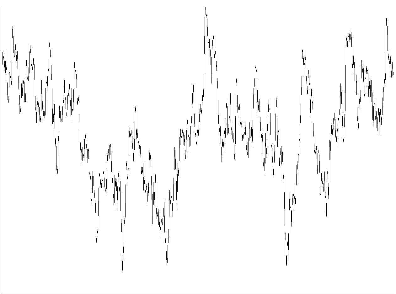
In electronics, noise is an unwanted disturbance in an electrical signal. Noise generated by electronic devices varies greatly as it is produced by several different effects. In particular, noise is inherent in physics, and central to thermodynamics. Any conductor with electrical resistance will generate thermal noise inherently. The final elimination of thermal noise in electronics can only be achieved cryogenically, and even then quantum noise would remain inherent. Electronic noise is a common component of noise in signal processing. In communication systems, noise is an error or undesired random disturbance of a useful information signal in a communication channel. The noise is a summation of unwanted or disturbing energy from natural and sometimes man-made sources. Noise is, however, typically distinguished from interference, for example in the signal-to-noise ratio (SNR), signal-to-interference ratio (SIR) and signal-to-noise plus interference ratio (SNIR) mea ... [...More Info...] [...Related Items...] OR: [Wikipedia] [Google] [Baidu] |
Resonant Frequency
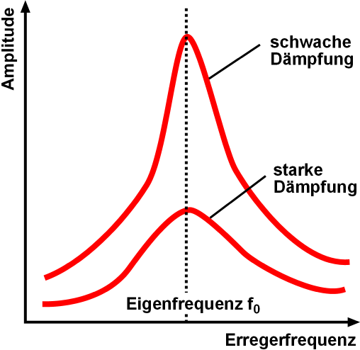
Resonance describes the phenomenon of increased amplitude that occurs when the frequency of an applied periodic force (or a Fourier component of it) is equal or close to a natural frequency of the system on which it acts. When an oscillating force is applied at a resonant frequency of a dynamic system, the system will oscillate at a higher amplitude than when the same force is applied at other, non-resonant frequencies. Frequencies at which the response amplitude is a relative maximum are also known as resonant frequencies or resonance frequencies of the system. Small periodic forces that are near a resonant frequency of the system have the ability to produce large amplitude oscillations in the system due to the storage of vibrational energy. Resonance phenomena occur with all types of vibrations or waves: there is mechanical resonance, orbital resonance, acoustic resonance, electromagnetic resonance, nuclear magnetic resonance (NMR), electron spin resonance (ESR) ... [...More Info...] [...Related Items...] OR: [Wikipedia] [Google] [Baidu] |
Sinusoidal
A sine wave, sinusoidal wave, or just sinusoid is a mathematical curve defined in terms of the '' sine'' trigonometric function, of which it is the graph. It is a type of continuous wave and also a smooth periodic function. It occurs often in mathematics, as well as in physics, engineering, signal processing and many other fields. Formulation Its most basic form as a function of time (''t'') is: y(t) = A\sin(2 \pi f t + \varphi) = A\sin(\omega t + \varphi) where: * ''A'', ''amplitude'', the peak deviation of the function from zero. * ''f'', '' ordinary frequency'', the ''number'' of oscillations (cycles) that occur each second of time. * ''ω'' = 2''f'', ''angular frequency'', the rate of change of the function argument in units of radians per second. * \varphi, '' phase'', specifies (in radians) where in its cycle the oscillation is at ''t'' = 0. When \varphi is non-zero, the entire waveform appears to be shifted in time by the amount ''φ''/''ω'' seconds. A negative valu ... [...More Info...] [...Related Items...] OR: [Wikipedia] [Google] [Baidu] |
Negative Differential Resistance
In electronics, negative resistance (NR) is a property of some electrical circuits and devices in which an increase in voltage across the device's terminals results in a decrease in electric current through it. This is in contrast to an ordinary resistor in which an increase of applied voltage causes a proportional increase in current due to Ohm's law, resulting in a positive electrical resistance, resistance. While a positive resistance consumes power from current passing through it, a negative resistance produces power. Under certain conditions it can increase the power of an electrical signal, amplifier, amplifying it. Negative resistance is an uncommon property which occurs in a few linear circuit, nonlinear electronic components. In a nonlinear device, two types of resistance can be defined: 'static' or 'absolute resistance', the ratio of voltage to current v / i, and ''differential resistance'', the ratio of a change in voltage to the resulting change in current \Delta v/ ... [...More Info...] [...Related Items...] OR: [Wikipedia] [Google] [Baidu] |
Biasing
In electronics, biasing is the setting of DC (direct current) operating conditions (current and voltage) of an active device in an amplifier. Many electronic devices, such as diodes, transistors and vacuum tubes, whose function is processing time-varying ( AC) signals, also require a steady (DC) current or voltage at their terminals to operate correctly. This current or voltage is called ''bias''. The AC signal applied to them is superposed on this DC bias current or voltage. The operating point of a device, also known as bias point, quiescent point, or Q-point, is the DC voltage or current at a specified terminal of an active device (a transistor or vacuum tube) with no input signal applied. A bias circuit is a portion of the device's circuit which supplies this steady current or voltage. Overview In electronics, 'biasing' usually refers to a fixed DC voltage or current applied to a terminal of an electronic component such as a diode, transistor or vacuum tube in a circui ... [...More Info...] [...Related Items...] OR: [Wikipedia] [Google] [Baidu] |


