|
Vackář Oscillator
A Vackář oscillator is a wide range variable frequency oscillator (VFO) which has a near constant output amplitude over its frequency range. It is similar to a Colpitts oscillator or a Clapp oscillator, but those designs do not have a constant output amplitude when tuned. Invention In 1949, the Czech engineer Jiří Vackář published a paper on the design of stable variable-frequency oscillators (VFO). The paper discussed many stability issues such as variations with temperature, atmospheric pressure, component aging, and microphonics. For example, Vackář describes making inductors by first heating the wire and then winding the wire on a stable ceramic coil form. The resulting inductor has a temperature coefficient of 6 to 8 parts per million per degree Celsius. Vackář points out that common air variable capacitors have a stability of 2 parts per thousand; to build a VFO with a stability of 50 parts per million requires that the variable capacitor is only 1/40 of the t ... [...More Info...] [...Related Items...] OR: [Wikipedia] [Google] [Baidu] |
Seiler Oscillator
The Seiler oscillator is an LC circuit, LC electronic oscillator. It was presented in 1941 by E. O. Seiler. The original implementation used a vacuum tube in an Electron-coupled oscillator circuit. Like the Clapp oscillator and the Vackář oscillator it is a variation of the Colpitts oscillator. It uses a voltage divider made of two capacitors, named C3 and C4 in the original schematic. The tuning capacitor C1 is parallel to the inductance L1 of the LC circuit. In an Clapp oscillator, the tuning capacitor is in series to the inductance. The variable capacitor C2 controls the coupling between the tube and tank (LC circuit). Practical example The schematic shows an example with component values.The Seiler oscillator uses a LC circuit L1, C1 that is connected via C2 to a capacitive voltage divider C3, C4 that connects to the amplifier Q1. C1 and C2 are calculated for inductance L1 having a unloaded Q factor of 250. Resistor R1 sets the collector current to 0.5mA with no oscillatio ... [...More Info...] [...Related Items...] OR: [Wikipedia] [Google] [Baidu] |
Resonant Frequency
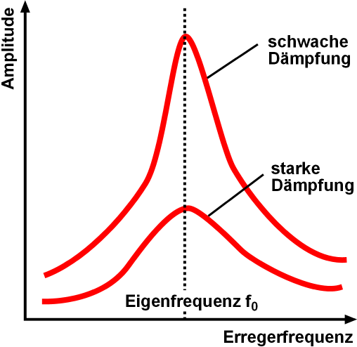
Resonance describes the phenomenon of increased amplitude that occurs when the frequency of an applied periodic force (or a Fourier component of it) is equal or close to a natural frequency of the system on which it acts. When an oscillating force is applied at a resonant frequency of a dynamic system, the system will oscillate at a higher amplitude than when the same force is applied at other, non-resonant frequencies. Frequencies at which the response amplitude is a relative maximum are also known as resonant frequencies or resonance frequencies of the system. Small periodic forces that are near a resonant frequency of the system have the ability to produce large amplitude oscillations in the system due to the storage of vibrational energy. Resonance phenomena occur with all types of vibrations or waves: there is mechanical resonance, orbital resonance, acoustic resonance, electromagnetic resonance, nuclear magnetic resonance (NMR), electron spin resonance (ESR) and reson ... [...More Info...] [...Related Items...] OR: [Wikipedia] [Google] [Baidu] |
Transconductance
Transconductance (for transfer conductance), also infrequently called mutual conductance, is the electrical characteristic relating the current through the output of a device to the voltage across the input of a device. Conductance is the reciprocal of resistance. Transadmittance (or transfer admittance) is the AC equivalent of transconductance. Definition Transconductance is very often denoted as a conductance, ''g''m, with a subscript, m, for ''mutual''. It is defined as follows: :g_m = \frac For small signal alternating current, the definition is simpler: :g_m = \frac The SI unit for transconductance is the siemens, with the symbol S, as in conductance. Transresistance Transresistance (for transfer resistance), also infrequently referred to as mutual resistance, is the dual of transconductance. It refers to the ratio between a change of the voltage at two output points and a related change of current through two input points, and is notated as ''r''m: :r_m = \frac ... [...More Info...] [...Related Items...] OR: [Wikipedia] [Google] [Baidu] |
Tuned Circuit
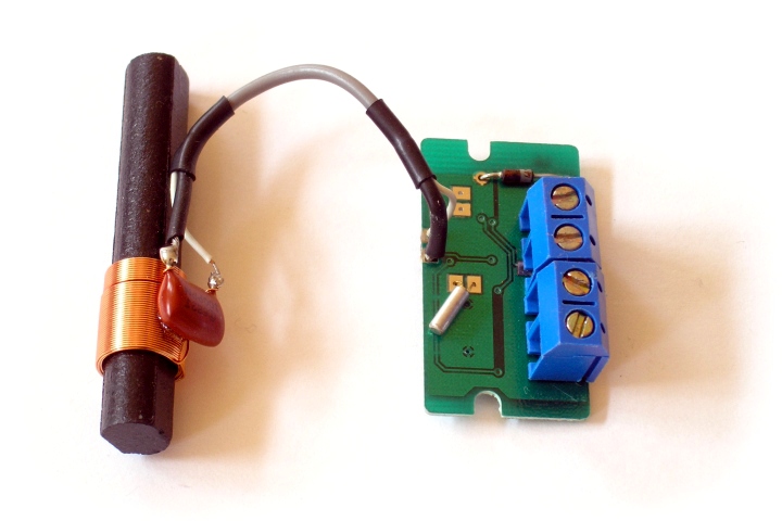
An LC circuit, also called a resonant circuit, tank circuit, or tuned circuit, is an electric circuit consisting of an inductor, represented by the letter L, and a capacitor, represented by the letter C, connected together. The circuit can act as an electrical resonator, an electrical analogue of a tuning fork, storing energy oscillating at the circuit's resonant frequency. LC circuits are used either for generating signals at a particular frequency, or picking out a signal at a particular frequency from a more complex signal; this function is called a bandpass filter. They are key components in many electronic devices, particularly radio equipment, used in circuits such as oscillators, filters, tuners and frequency mixers. An LC circuit is an idealized model since it assumes there is no dissipation of energy due to resistance. Any practical implementation of an LC circuit will always include loss resulting from small but non-zero resistance within the components and conn ... [...More Info...] [...Related Items...] OR: [Wikipedia] [Google] [Baidu] |
Resonant Circuit
An LC circuit, also called a resonant circuit, tank circuit, or tuned circuit, is an electric circuit consisting of an inductor, represented by the letter L, and a capacitor, represented by the letter C, connected together. The circuit can act as an electrical resonator, an electrical analogue of a tuning fork, storing energy oscillating at the circuit's resonant frequency. LC circuits are used either for generating signals at a particular frequency, or picking out a signal at a particular frequency from a more complex signal; this function is called a bandpass filter. They are key components in many electronic devices, particularly radio equipment, used in circuits such as oscillators, filters, tuners and frequency mixers. An LC circuit is an idealized model since it assumes there is no dissipation of energy due to resistance. Any practical implementation of an LC circuit will always include loss resulting from small but non-zero resistance within the components and connec ... [...More Info...] [...Related Items...] OR: [Wikipedia] [Google] [Baidu] |
JFET
The junction-gate field-effect transistor (JFET) is one of the simplest types of field-effect transistor. JFETs are three-terminal semiconductor devices that can be used as electronically controlled switches or resistors, or to build amplifiers. Unlike bipolar junction transistors, JFETs are exclusively voltage-controlled in that they do not need a biasing current. Electric charge flows through a semiconducting channel between ''source'' and ''drain'' terminals. By applying a reverse bias voltage to a ''gate'' terminal, the channel is ''pinched'', so that the electric current is impeded or switched off completely. A JFET is usually conducting when there is zero voltage between its gate and source terminals. If a potential difference of the proper polarity is applied between its gate and source terminals, the JFET will be more resistive to current flow, which means less current would flow in the channel between the source and drain terminals. JFETs are sometimes referred to as ... [...More Info...] [...Related Items...] OR: [Wikipedia] [Google] [Baidu] |
Lampkin Oscillator
Lampkin is an English surname. Notable persons with this surname * Arthur Lampkin (born circa 1938), English former professional motorcycle racer * Charles Lampkin (1913–1989), American actor, musician and lecturer * Chrissy Lampkin, participant of an American reality television series Love & Hip Hop * Daisy Elizabeth Adams Lampkin (1883–1965), American suffragette * Dougie Lampkin (born 1976), English motorcycle trials rider * Jeff Lampkin (born 1959), American former professional boxer * Kevin Lampkin (born 1972), English former professional footballer * Martin Lampkin (1950–2016), English former professional motorcycle competitor * Nahru Lampkin (born 1962), American entertainer, musician, street performer, entrepreneur * Ray Lampkin (born 1948), American former professional boxer * Sheilla Lampkin (1945–2016), American politician * Tom Lampkin (born 1964), American former catcher in Major League Baseball * Calvin Lampkin (1969-2001), American former professiona ... [...More Info...] [...Related Items...] OR: [Wikipedia] [Google] [Baidu] |
Barkhausen Stability Criterion
In electronics, the Barkhausen stability criterion is a mathematical condition to determine when a linear electronic circuit will oscillate. It was put forth in 1921 by German physicist Heinrich Georg Barkhausen (1881–1956). It is widely used in the design of electronic oscillators, and also in the design of general negative feedback circuits such as op amps, to prevent them from oscillating. Limitations Barkhausen's criterion applies to linear circuits with a feedback loop. It cannot be applied directly to active elements with negative resistance like tunnel diode oscillators. The kernel of the criterion is that a complex pole pair must be placed on the imaginary axis of the complex frequency plane if steady state oscillations should take place. In the real world, it is impossible to balance on the imaginary axis, so in practice a steady-state oscillator is a non-linear circuit: * It needs to have positive feedback. * The loop gain is at unity (, \beta A, = 1\,). Cr ... [...More Info...] [...Related Items...] OR: [Wikipedia] [Google] [Baidu] |
Variable Frequency Oscillator
A variable frequency oscillator (VFO) in electronics is an oscillator whose frequency can be tuned (i.e., varied) over some range. It is a necessary component in any tunable radio transmitter or receiver that works by the superheterodyne principle, and controls the frequency to which the apparatus is tuned. Purpose In a simple superheterodyne receiver, the incoming radio frequency signal (at frequency f_) from the antenna is ''mixed'' with the VFO output signal tuned to f_, producing an intermediate frequency (IF) signal that can be processed downstream to extract the modulated information. Depending on the receiver design, the IF signal frequency is chosen to be either the sum of the two frequencies at the mixer inputs ( up-conversion), f_+f_ or more commonly, the difference frequency (down-conversion), f_-f_. In addition to the desired ''IF'' signal and its unwanted image (the mixing product of opposite sign above), the mixer output will also contain the two original frequenci ... [...More Info...] [...Related Items...] OR: [Wikipedia] [Google] [Baidu] |
Insertion Loss
In telecommunications, insertion loss is the loss of signal power resulting from the insertion of a device in a transmission line or optical fiber and is usually expressed in decibels (dB). If the power transmitted to the load before insertion is ''P''T and the power received by the load after insertion is ''P''R, then the insertion loss in decibels is given by, :IL(\mathrm) = 10 \log_ Electronic filters Insertion loss is a figure of merit for an electronic filter and this data is generally specified with a filter. Insertion loss is defined as a ratio of the signal level in a test configuration without the filter installed (\left\vert V_1 \right\vert) to the signal level with the filter installed (\left\vert V_2 \right\vert). This ratio is described in decibels by the following equation: :\mbox = 10 \log_ = 20 \log_ For passive filters, \left\vert V_2 \right\vert will be smaller than \left\vert V_1 \right\vert. In this case, the insertion loss is positive and measures ... [...More Info...] [...Related Items...] OR: [Wikipedia] [Google] [Baidu] |
Q Factor
In physics and engineering, the quality factor or ''Q'' factor is a dimensionless parameter that describes how underdamped an oscillator or resonator is. It is defined as the ratio of the initial energy stored in the resonator to the energy lost in one radian of the cycle of oscillation. Q factor is alternatively defined as the ratio of a resonator's centre frequency to its bandwidth when subject to an oscillating driving force. These two definitions give numerically similar, but not identical, results. Higher ''Q'' indicates a lower rate of energy loss and the oscillations die out more slowly. A pendulum suspended from a high-quality bearing, oscillating in air, has a high ''Q'', while a pendulum immersed in oil has a low one. Resonators with high quality factors have low damping, so that they ring or vibrate longer. Explanation The Q factor is a parameter that describes the resonance behavior of an underdamped harmonic oscillator (resonator). Sinusoidally driven resonators ha ... [...More Info...] [...Related Items...] OR: [Wikipedia] [Google] [Baidu] |


