|
Spur Gear
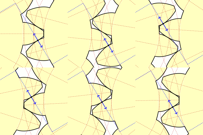
Spur gears or straight-cut gears are the simplest type of gear. They consist of a cylinder or disk with teeth projecting radially. Viewing the gear at 90 degrees from the shaft length (side on) the tooth faces are straight and aligned parallel to the axis of rotation. Looking down the length of the shaft, a tooth's cross section is usually not triangular. Instead of being straight (as in a triangle) the sides of the cross section have a curved form (usually involute and less commonly cycloidal) to achieve a constant drive ratio. Spur gears mesh together correctly only if fitted to parallel shafts. No axial thrust is created by the tooth loads. Spur gears are excellent at moderate speeds but tend to be noisy at high speeds. Spur gear can be classified into two pressure angles, 20° being the current industry standard and 14½° being the former (often found in older equipment). Spur gear teeth are manufactured as either involute In mathematics, an involute (also known as an ... [...More Info...] [...Related Items...] OR: [Wikipedia] [Google] [Baidu] |
Spur Gear 12mm, 18t
A spur is a metal tool designed to be worn in pairs on the heels of riding boots for the purpose of directing a horse or other animal to move forward or laterally while riding. It is usually used to refine the riding aids (commands) and to back up the natural aids (the leg, seat, hands, and voice). The spur is used in many equestrian disciplines. Most equestrian organizations have rules in about spur design and use and penalties for using spurs in any manner that constitutes animal abuse. Etymology This very old word derives from Anglo-Saxon ''spura, spora'', related to ''spornan, spurnan'', to kick, ''spurn''; cf. Medieval High German ''Sporn'', modern German ''Sporn'', Dutch ''spoor''. The generalized sense of "anything that urges on, stimulus" is recorded in English from'' circa'' 1390. Design The parts of a spur include: *The "yoke", "branch", or "heel band", which wraps around the heel of the boot. *The "shank" or "neck", which extends from the back of the yoke and is the ... [...More Info...] [...Related Items...] OR: [Wikipedia] [Google] [Baidu] |
Gear
A gear is a rotating circular machine part having cut teeth or, in the case of a cogwheel or gearwheel, inserted teeth (called ''cogs''), which mesh with another (compatible) toothed part to transmit (convert) torque and speed. The basic principle behind the operation of gears is analogous to the basic principle of levers. A gear may also be known informally as a cog. Geared devices can change the speed, torque, and direction of a power source. Gears of different sizes produce a change in torque, creating a mechanical advantage, through their ''gear ratio'', and thus may be considered a simple machine. The rotational speeds, and the torques, of two meshing gears differ in proportion to their diameters. The teeth on the two meshing gears all have the same shape. Two or more meshing gears, working in a sequence, are called a gear train or a '' transmission''. The gears in a transmission are analogous to the wheels in a crossed, belt pulley system. An advantage of gears is tha ... [...More Info...] [...Related Items...] OR: [Wikipedia] [Google] [Baidu] |
Rotation Around A Fixed Axis
Rotation around a fixed axis is a special case of rotational motion. The fixed-axis hypothesis excludes the possibility of an axis changing its orientation and cannot describe such phenomena as wobbling or precession. According to Euler's rotation theorem, simultaneous rotation along a number of stationary axes at the same time is impossible; if two rotations are forced at the same time, a new axis of rotation will appear. This article assumes that the rotation is also stable, such that no torque is required to keep it going. The kinematics and dynamics of rotation around a fixed axis of a rigid body are mathematically much simpler than those for free rotation of a rigid body; they are entirely analogous to those of linear motion along a single fixed direction, which is not true for ''free rotation of a rigid body''. The expressions for the kinetic energy of the object, and for the forces on the parts of the object, are also simpler for rotation around a fixed axis, than for ... [...More Info...] [...Related Items...] OR: [Wikipedia] [Google] [Baidu] |
Involute Gear
The involute gear profile is the most commonly used system for gearing today, with cycloid gearing still used for some specialties such as clocks. In an involute gear, the profiles of the teeth are ''involutes of a circle.'' The involute of a circle is the spiraling curve traced by the end of an imaginary taut string unwinding itself from that stationary circle called the base circle, or (equivalently) a triangle wave projected on the circumference of a circle. The involute gear profile was a fundamental advance in machine design, since unlike with other gear systems, the tooth profile of an involute gear depends only on the number of teeth on the gear, pressure angle, and pitch. That is, a gear's profile does not depend on the gear it mates with. Thus, n and m tooth involute spur gears with a given pressure angle and pitch will mate correctly, independently of n and m. This dramatically reduces the number of shapes of gears that need to be manufactured and kept in inventory. I ... [...More Info...] [...Related Items...] OR: [Wikipedia] [Google] [Baidu] |
Cycloid Gear
The cycloidal gear profile is a form of toothed gear used in mechanical clocks, rather than the involute gear form used for most other gears. The gear tooth profile is based on the epicycloid and hypocycloid curves, which are the curves generated by a circle rolling around the outside and inside of another circle, respectively. When two toothed gears mesh, an imaginary circle, the ''pitch circle'', can be drawn around the centre of either gear through the point where their teeth make contact. The curves of the teeth outside the pitch circle are known as the ''addenda'', and the curves of the tooth spaces inside the pitch circle are known as the ''dedenda''. An addendum of one gear rests inside a dedendum of the other gear. In the cycloidal gears, the addenda of the wheel teeth are convex epi-cycloidal and the dedenda of the pinion are concave hypocycloidal curves generated by the same generating circle. This ensures that the motion of one gear is transferred to the other at l ... [...More Info...] [...Related Items...] OR: [Wikipedia] [Google] [Baidu] |
Gear Train
A gear train is a mechanical system formed by mounting gears on a frame so the teeth of the gears engage. Gear teeth are designed to ensure the pitch circles of engaging gears roll on each other without slipping, providing a smooth transmission of rotation from one gear to the next. Features of gears and gear trains include: * The gear ratio of the pitch circles of mating gears defines the speed ratio and the mechanical advantage of the gear set. * A planetary gear train provides high gear reduction in a compact package. * It is possible to design gear teeth for gears that are non-circular, yet still transmit torque smoothly. * The speed ratios of chain and belt drives are computed in the same way as gear ratios. See bicycle gearing. The transmission of rotation between contacting toothed wheels can be traced back to the Antikythera mechanism of Greece and the south-pointing chariot of China. Illustrations by the Renaissance scientist Georgius Agricola show gear trains with ... [...More Info...] [...Related Items...] OR: [Wikipedia] [Google] [Baidu] |
Pressure Angle
Pressure angle in relation to gear teeth, also known as the angle of obliquity, is the angle between the tooth face and the gear wheel tangent. It is more precisely the angle at a pitch point between the line of pressure (which is normal to the tooth surface) and the plane tangent to the pitch surface. The pressure angle gives the direction normal to the tooth profile. The pressure angle is equal to the profile angle at the standard pitch circle and can be termed the "standard" pressure angle at that point. Standard values are 14.5 and 20 degrees. Earlier gears with pressure angle 14.5 were commonly used because the cosine is larger for a smaller angle, providing more power transmission and less pressure on the bearing; however, teeth with smaller pressure angles are weaker. To run gears together properly their pressure angles must be matched. The pressure angle is also the angle of the sides of the trapezoidal teeth on the corresponding rack. The force transmitted during the m ... [...More Info...] [...Related Items...] OR: [Wikipedia] [Google] [Baidu] |
Involute
In mathematics, an involute (also known as an evolvent) is a particular type of curve that is dependent on another shape or curve. An involute of a curve is the locus of a point on a piece of taut string as the string is either unwrapped from or wrapped around the curve. It is a class of curves coming under the roulette family of curves. The evolute of an involute is the original curve. The notions of the involute and evolute of a curve were introduced by Christiaan Huygens in his work titled '' Horologium oscillatorium sive de motu pendulorum ad horologia aptato demonstrationes geometricae'' (1673). Involute of a parameterized curve Let \vec c(t),\; t\in _1,t_2 be a regular curve in the plane with its curvature nowhere 0 and a\in (t_1,t_2), then the curve with the parametric representation \vec C_a(t)=\vec c(t) -\frac\; \int_a^t, \vec c'(w), \; dw is an ''involute'' of the given curve. Adding an arbitrary but fixed number l_0 to the integral \Bigl(\int_a^t, \ve ... [...More Info...] [...Related Items...] OR: [Wikipedia] [Google] [Baidu] |
Undercut (manufacturing)
In manufacturing, an undercut is a special type of recessed surface that is inaccessible using a straight tool. In turning, it refers to a recess in a diameter generally on the inside diameter of the part. In milling, it refers to a feature which is not visible when the part is viewed from the spindle. In molding, it refers to a feature that cannot be molded using only a single pull mold. In printed circuit board construction, it refers to the portion of the copper that is etched away under the photoresist. Turning On turned parts an undercut is also known as a ''neck'' or "relief groove". They are often used at the end of the threaded portion of a shaft or screw to provide clearance for the cutting tool. Molding Undercut - Any indentation or protrusion in a shape that will prevent its withdrawal from a one-piece mold. Milling In milling the spindle is where a cutting tool is mounted. In some situations material must be cut from a direction where the feature can not b ... [...More Info...] [...Related Items...] OR: [Wikipedia] [Google] [Baidu] |


