|
Spiral Antenna
In microwave systems, a spiral antenna is a type of RF antenna. It is shaped as a two-arm spiral, or more arms may be used. Spiral antennas were first described in 1956. ''Logarithmic'' spiral antennas belong to the class of frequency independent antennas; the driving point impedance, radiation pattern and polarization of such antennas remain unchanged over a large bandwidth range. Spiral antennas are inherently circularly polarized with low gain. Antenna arrays can be used to increase the gain. Spiral antennas are reduced size antennas with its windings making it an extremely small structure. Lossy cavities are usually placed at the back to eliminate back lobes because a unidirectional pattern is usually preferred in such antennas. Spiral antennas are classified into different types; Archimedean spiral, logarithmic spiral, square spiral, and star spiral, etc. Archimedean spiral is the most popular configuration. Principle In general, antennas may operate in three different m ... [...More Info...] [...Related Items...] OR: [Wikipedia] [Google] [Baidu] |
Microwave
Microwave is a form of electromagnetic radiation with wavelengths ranging from about one meter to one millimeter corresponding to frequencies between 300 MHz and 300 GHz respectively. Different sources define different frequency ranges as microwaves; the above broad definition includes both UHF and EHF (millimeter wave) bands. A more common definition in radio-frequency engineering is the range between 1 and 100 GHz (wavelengths between 0.3 m and 3 mm). In all cases, microwaves include the entire SHF band (3 to 30 GHz, or 10 to 1 cm) at minimum. Frequencies in the microwave range are often referred to by their IEEE radar band designations: S, C, X, Ku, K, or Ka band, or by similar NATO or EU designations. The prefix ' in ''microwave'' is not meant to suggest a wavelength in the micrometer range. Rather, it indicates that microwaves are "small" (having shorter wavelengths), compared to the radio waves used prior to microwave te ... [...More Info...] [...Related Items...] OR: [Wikipedia] [Google] [Baidu] |
Antenna (radio)
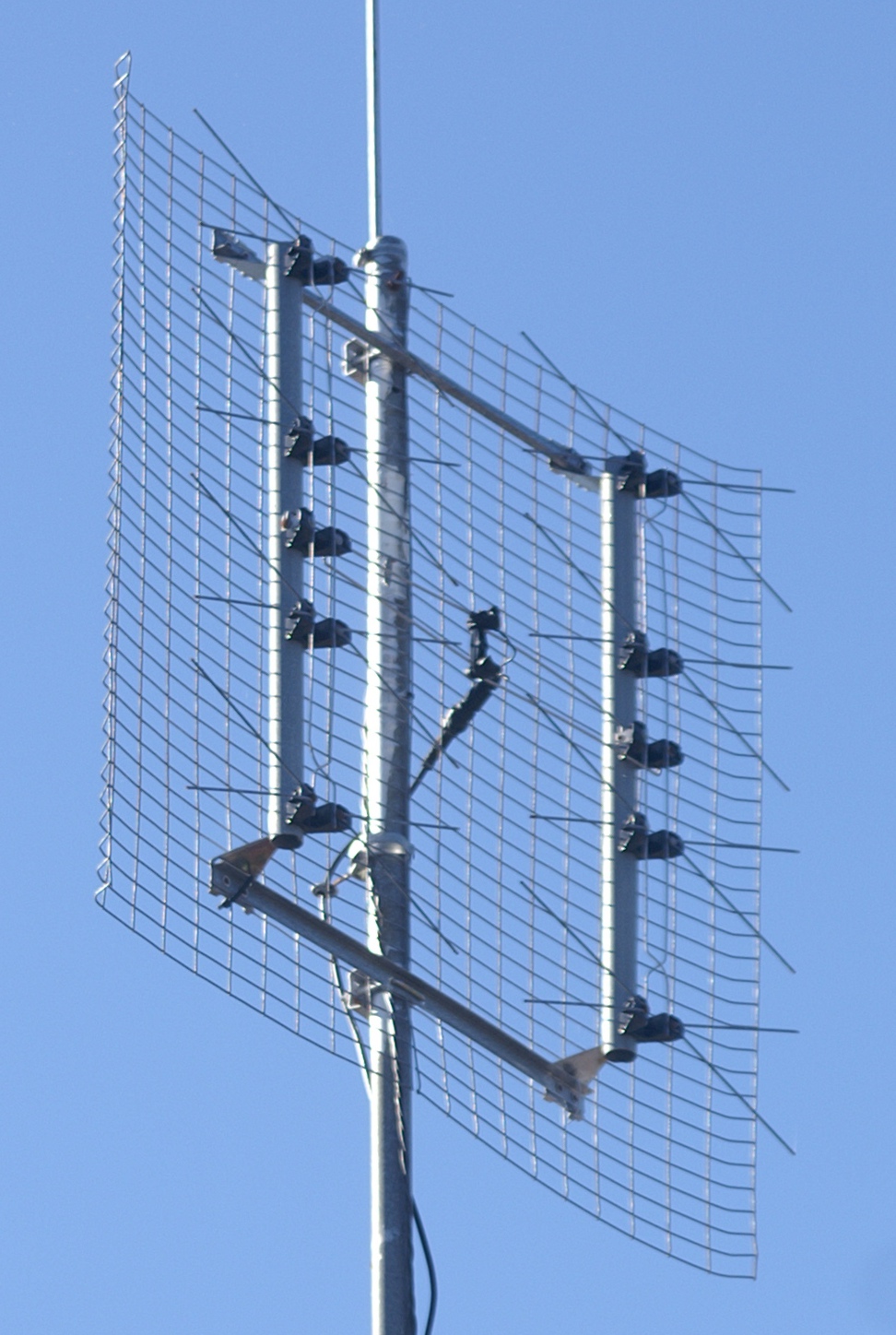
In radio engineering, an antenna or aerial is the interface between radio waves propagating through space and electric currents moving in metal conductors, used with a transmitter or receiver. In transmission, a radio transmitter supplies an electric current to the antenna's terminals, and the antenna radiates the energy from the current as electromagnetic wave In physics, electromagnetic radiation (EMR) consists of waves of the electromagnetic (EM) field, which propagate through space and carry momentum and electromagnetic radiant energy. It includes radio waves, microwaves, infrared, (visib ...s (radio waves). In Receiver (radio), reception, an antenna intercepts some of the power of a radio wave in order to produce an electric current at its terminals, that is applied to a receiver to be Amplifier, amplified. Antennas are essential components of all radio equipment. An antenna is an array of conductor (material), conductors (Driven element, elements), elect ... [...More Info...] [...Related Items...] OR: [Wikipedia] [Google] [Baidu] |
Spiral
In mathematics, a spiral is a curve which emanates from a point, moving farther away as it revolves around the point. Helices Two major definitions of "spiral" in the American Heritage Dictionary are:Spiral ''American Heritage Dictionary of the English Language'', Houghton Mifflin Company, Fourth Edition, 2009. # a curve on a plane that winds around a fixed center point at a continuously increasing or decreasing distance from the point. # a three-dimensional curve that turns around an axis at a constant or continuously varying distance while moving parallel to the axis; a . The first definition describes a |
Antenna Gain
In electromagnetics, an antenna's gain is a key performance parameter which combines the antenna's directivity and radiation efficiency. The term ''power gain'' has been deprecated by IEEE. In a transmitting antenna, the gain describes how well the antenna converts input power into radio waves headed in a specified direction. In a receiving antenna, the gain describes how well the antenna converts radio waves arriving from a specified direction into electrical power. When no direction is specified, gain is understood to refer to the peak value of the gain, the gain in the direction of the antenna's main lobe. A plot of the gain as a function of direction is called the antenna pattern or radiation pattern. It is not to be confused with directivity, which does ''not'' take an antenna's radiation efficiency into account. Gain or 'absolute gain' is defined as "The ratio of the radiation intensity in a given direction to the radiation intensity that would be produced if the p ... [...More Info...] [...Related Items...] OR: [Wikipedia] [Google] [Baidu] |
Antenna Array
An antenna array (or array antenna) is a set of multiple connected antennas which work together as a single antenna, to transmit or receive radio waves. The individual antennas (called ''elements'') are usually connected to a single receiver or transmitter by feedlines that feed the power to the elements in a specific phase relationship. The radio waves radiated by each individual antenna combine and superpose, adding together ( interfering constructively) to enhance the power radiated in desired directions, and cancelling ( interfering destructively) to reduce the power radiated in other directions. Similarly, when used for receiving, the separate radio frequency currents from the individual antennas combine in the receiver with the correct phase relationship to enhance signals received from the desired directions and cancel signals from undesired directions. More sophisticated array antennas may have multiple transmitter or receiver modules, each connected to a separate a ... [...More Info...] [...Related Items...] OR: [Wikipedia] [Google] [Baidu] |
Electrical Permittivity
In electromagnetism, the absolute permittivity, often simply called permittivity and denoted by the Greek letter ''ε'' (epsilon), is a measure of the electric polarizability of a dielectric. A material with high permittivity polarizes more in response to an applied electric field than a material with low permittivity, thereby storing more energy in the material. In electrostatics, the permittivity plays an important role in determining the capacitance of a capacitor. In the simplest case, the electric displacement field D resulting from an applied electric field E is :\mathbf = \varepsilon \mathbf. More generally, the permittivity is a thermodynamic function of state. It can depend on the frequency, magnitude, and direction of the applied field. The SI unit for permittivity is farad per meter (F/m). The permittivity is often represented by the relative permittivity ''ε''r which is the ratio of the absolute permittivity ''ε'' and the vacuum permittivity ''ε''0 :\kappa = ... [...More Info...] [...Related Items...] OR: [Wikipedia] [Google] [Baidu] |
Logarithmic Spiral
A logarithmic spiral, equiangular spiral, or growth spiral is a self-similar spiral curve that often appears in nature. The first to describe a logarithmic spiral was Albrecht Dürer (1525) who called it an "eternal line" ("ewige Linie"). More than a century later, the curve was discussed by Descartes (1638), and later extensively investigated by Jacob Bernoulli, who called it ''Spira mirabilis'', "the marvelous spiral". The logarithmic spiral can be distinguished from the Archimedean spiral by the fact that the distances between the turnings of a logarithmic spiral increase in geometric progression, while in an Archimedean spiral these distances are constant. Definition In polar coordinates (r, \varphi) the logarithmic spiral can be written as r = ae^,\quad \varphi \in \R, or \varphi = \frac \ln \frac, with e being the base of natural logarithms, and a > 0, k\ne 0 being real constants. In Cartesian coordinates The logarithmic spiral with the polar equation r = a e^ ... [...More Info...] [...Related Items...] OR: [Wikipedia] [Google] [Baidu] |
Balanced Line
In telecommunications and professional audio, a balanced line or balanced signal pair is a circuit consisting of two conductors of the same type, both of which have equal impedances along their lengths and equal impedances to ground and to other circuits. The chief advantage of the balanced line format is good rejection of common-mode noise and interference when fed to a differential device such as a transformer or differential amplifier.G. Ballou, ''Handbook for Sound Engineers'', Fifth Edition, Taylor & Francis, 2015, p. 1267–1268. As prevalent in sound recording and reproduction, balanced lines are referred to as balanced audio. Common forms of balanced line are twin-lead, used for radio frequency signals and twisted pair, used for lower frequencies. They are to be contrasted to unbalanced lines, such as coaxial cable, which is designed to have its return conductor connected to ground, or circuits whose return conductor actually is ground (see earth-return telegraph). Bal ... [...More Info...] [...Related Items...] OR: [Wikipedia] [Google] [Baidu] |
Coaxial Cable
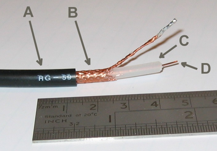
Coaxial cable, or coax (pronounced ) is a type of electrical cable consisting of an inner conductor surrounded by a concentric conducting shield, with the two separated by a dielectric ( insulating material); many coaxial cables also have a protective outer sheath or jacket. The term ''coaxial'' refers to the inner conductor and the outer shield sharing a geometric axis. Coaxial cable is a type of transmission line, used to carry high-frequency electrical signals with low losses. It is used in such applications as telephone trunk lines, broadband internet networking cables, high-speed computer data busses, cable television signals, and connecting radio transmitters and receivers to their antennas. It differs from other shielded cables because the dimensions of the cable and connectors are controlled to give a precise, constant conductor spacing, which is needed for it to function efficiently as a transmission line. Coaxial cable was used in the first (1858) and followin ... [...More Info...] [...Related Items...] OR: [Wikipedia] [Google] [Baidu] |
Balun
A balun (from "balanced to unbalanced", originally, but now dated from "balancing unit") is an electrical device that allows balanced and unbalanced lines to be interfaced without disturbing the impedance arrangement of either line. A balun can take many forms and may include devices that also transform impedances but need not do so. Sometimes, in the case of transformer baluns, they use magnetic coupling but need not do so. Common-mode chokes are also used as baluns and work by eliminating, rather than rejecting, common mode signals. Types of balun Classical transformer type In classical transformers, there are two electrically separate windings of wire coils around the transformer's core. The advantage of transformer-type over other types of balun is that the electrically separate windings for input and output allow these baluns to connect circuits whose ground-level voltages are subject to ground loops or are otherwise electrically incompatible; for that reason they ... [...More Info...] [...Related Items...] OR: [Wikipedia] [Google] [Baidu] |


