|
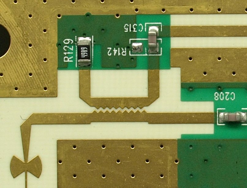
Slow-wave Coupler
A slow-wave coupler is a directional coupler consisting of microstrip lines in which there is a corrugation in the inner edges of the transmission lines where the coupling takes place. The objective is to reduce the phase velocity The phase velocity of a wave is the rate at which the wave propagates in any medium. This is the velocity at which the phase of any one frequency component of the wave travels. For such a component, any given phase of the wave (for example, ... of the odd mode of the coupled lines to match that of the even mode, and thereby to improve the isolation and directivity of the coupler. Microwave technology {{Technology-stub ... [...More Info...] [...Related Items...] OR: [Wikipedia] [Google] [Baidu] |
Microstrip Sawtooth Directional Coupler
Microstrip is a type of electrical transmission line which can be fabricated with any technology where a conductor is separated from a ground plane by a dielectric layer known as the substrate. Microstrip lines are used to convey microwave-frequency signals. Typical realisation technologies are printed circuit board, alumina coated with a dielectric layer or sometimes silicon or some other similar technologies. Microwave components such as antennas, couplers, filters, power dividers etc. can be formed from microstrip, with the entire device existing as the pattern of metallization on the substrate. Microstrip is thus much less expensive than traditional waveguide technology, as well as being far lighter and more compact. Microstrip was developed by ITT laboratories as a competitor to stripline (first published by Grieg and Engelmann in the December 1952 IRE proceedings). The disadvantages of microstrip compared with waveguide are the generally lower power handling capaci ... [...More Info...] [...Related Items...] OR: [Wikipedia] [Google] [Baidu] |
Directional Coupler
Power dividers (also power splitters and, when used in reverse, power combiners) and directional couplers are passive devices used mostly in the field of radio technology. They couple a defined amount of the electromagnetic power in a transmission line to a port enabling the signal to be used in another circuit. An essential feature of directional couplers is that they only couple power flowing in one direction. Power entering the output port is coupled to the isolated port but not to the coupled port. A directional coupler designed to split power equally between two ports is called a hybrid coupler. Directional couplers are most frequently constructed from two coupled transmission lines set close enough together such that energy passing through one is coupled to the other. This technique is favoured at the microwave frequencies where transmission line designs are commonly used to implement many circuit elements. However, lumped component devices are also possible at lower ... [...More Info...] [...Related Items...] OR: [Wikipedia] [Google] [Baidu] |
Microstrip
Microstrip is a type of electrical transmission line which can be fabricated with any technology where a conductor is separated from a ground plane by a dielectric layer known as the substrate. Microstrip lines are used to convey microwave-frequency signals. Typical realisation technologies are printed circuit board, alumina coated with a dielectric layer or sometimes silicon or some other similar technologies. Microwave components such as antennas, couplers, filters, power dividers etc. can be formed from microstrip, with the entire device existing as the pattern of metallization on the substrate. Microstrip is thus much less expensive than traditional waveguide technology, as well as being far lighter and more compact. Microstrip was developed by ITT laboratories as a competitor to stripline (first published by Grieg and Engelmann in the December 1952 IRE proceedings). The disadvantages of microstrip compared with waveguide are the generally lower power handling capacity, ... [...More Info...] [...Related Items...] OR: [Wikipedia] [Google] [Baidu] |
Transmission Line
In electrical engineering, a transmission line is a specialized cable or other structure designed to conduct electromagnetic waves in a contained manner. The term applies when the conductors are long enough that the wave nature of the transmission must be taken into account. This applies especially to radio-frequency engineering because the short wavelengths mean that wave phenomena arise over very short distances (this can be as short as millimetres depending on frequency). However, the theory of transmission lines was historically developed to explain phenomena on very long telegraph lines, especially submarine telegraph cables. Transmission lines are used for purposes such as connecting radio transmitters and receivers with their antennas (they are then called feed lines or feeders), distributing cable television signals, trunklines routing calls between telephone switching centres, computer network connections and high speed computer data buses. RF engineers co ... [...More Info...] [...Related Items...] OR: [Wikipedia] [Google] [Baidu] |
Phase Velocity
The phase velocity of a wave is the rate at which the wave propagates in any medium. This is the velocity at which the phase of any one frequency component of the wave travels. For such a component, any given phase of the wave (for example, the crest) will appear to travel at the phase velocity. The phase velocity is given in terms of the wavelength (lambda) and time period as :v_\mathrm = \frac. Equivalently, in terms of the wave's angular frequency , which specifies angular change per unit of time, and wavenumber (or angular wave number) , which represent the angular change per unit of space, :v_\mathrm = \frac. To gain some basic intuition for this equation, we consider a propagating (cosine) wave . We want to see how fast a particular phase of the wave travels. For example, we can choose , the phase of the first crest. This implies , and so . Formally, we let the phase and see immediately that and . So, it immediately follows that : \frac = -\frac \frac = \fr ... [...More Info...] [...Related Items...] OR: [Wikipedia] [Google] [Baidu] |


.gif)