|
Propeller Theory
Propeller theory is the science governing the design of efficient propellers. A propeller is the most common propulsor on ships, and on small aircraft. History In the second half of the nineteenth century, several theories were developed. The momentum theory or disk actuator theory – a theory describing a mathematical model of an ideal propeller – was developed by William John Macquorn Rankine, W.J.M. Rankine (1865), Alfred George Greenhill (1888) and Robert Edmund Froude (1889). The propeller is modelled as an infinitely thin disc, inducing a constant velocity along the axis of rotation. This disc creates a flow around the propeller. Under certain mathematical premises of the fluid, there can be extracted a mathematical connection between power, radius of the propeller, torque and induced velocity. Friction is not included. The blade element theory (BET) is a mathematical process originally designed by William Froude father of Robert Edmund Froude (1878), David W. Taylo ... [...More Info...] [...Related Items...] OR: [Wikipedia] [Google] [Baidu] |
Propeller
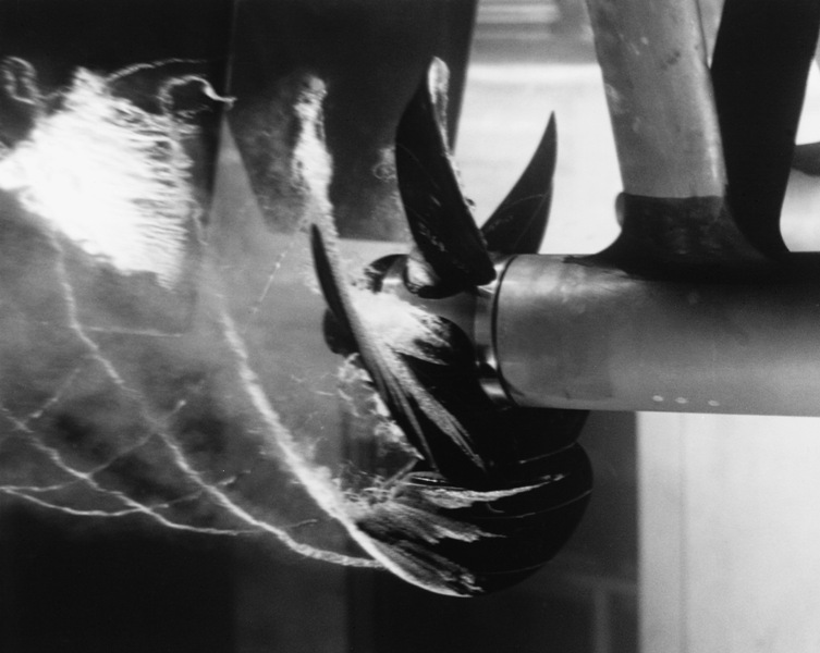
A propeller (colloquially often called a screw if on a ship or an airscrew if on an aircraft) is a device with a rotating hub and radiating blades that are set at a pitch to form a helical spiral which, when rotated, exerts linear thrust upon a working fluid such as water or air. Propellers are used to pump fluid through a pipe or duct, or to create thrust to propel a boat through water or an aircraft through air. The blades are specially shaped so that their rotational motion through the fluid causes a pressure difference between the two surfaces of the blade by Bernoulli's principle which exerts force on the fluid. Most marine propellers are screw propellers with helical blades rotating on a propeller shaft (ship), propeller shaft with an approximately horizontal axis. History Early developments The principle employed in using a screw propeller is derived from sculling. In sculling, a single blade is moved through an arc, from side to side taking care to keep presenting the ... [...More Info...] [...Related Items...] OR: [Wikipedia] [Google] [Baidu] |
Screw
A screw and a bolt (see '' Differentiation between bolt and screw'' below) are similar types of fastener typically made of metal and characterized by a helical ridge, called a ''male thread'' (external thread). Screws and bolts are used to fasten materials by the engagement of the screw thread with a similar ''female thread'' (internal thread) in a matching part. Screws are often self-threading (also known as self-tapping) where the thread cuts into the material when the screw is turned, creating an internal thread that helps pull fastened materials together and prevents pull-out. There are many screws for a variety of materials; materials commonly fastened by screws include wood, sheet metal, and plastic. Explanation A screw is a combination of simple machines: it is, in essence, an inclined plane wrapped around a central shaft, but the inclined plane (thread) also comes to a sharp edge around the outside, which acts as a wedge as it pushes into the fastened material, and th ... [...More Info...] [...Related Items...] OR: [Wikipedia] [Google] [Baidu] |
Lift Coefficient
In fluid dynamics, the lift coefficient () is a dimensionless quantity that relates the lift generated by a lifting body to the fluid density around the body, the fluid velocity and an associated reference area. A lifting body is a foil or a complete foil-bearing body such as a fixed-wing aircraft. is a function of the angle of the body to the flow, its Reynolds number and its Mach number. The section lift coefficient refers to the dynamic lift characteristics of a two-dimensional foil section, with the reference area replaced by the foil chord. Abbott, Ira H., and Doenhoff, Albert E. von: ''Theory of Wing Sections''. Section 1.2 Definitions The lift coefficient ''C''L is defined by :C_\mathrm L \equiv \frac = = , where L\, is the lift force, S\, is the relevant surface area and q\, is the fluid dynamic pressure, in turn linked to the fluid density \rho\,, and to the flow speed u\,. The choice of the reference surface should be specified since it is arbitrary. For examp ... [...More Info...] [...Related Items...] OR: [Wikipedia] [Google] [Baidu] |
Angle Of Attack
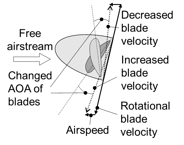
In fluid dynamics, angle of attack (AOA, α, or \alpha) is the angle between a reference line on a body (often the chord line of an airfoil) and the vector representing the relative motion between the body and the fluid through which it is moving. Angle of attack is the angle between the body's reference line and the oncoming flow. This article focuses on the most common application, the angle of attack of a wing or airfoil moving through air. In aerodynamics, angle of attack specifies the angle between the chord line of the wing of a fixed-wing aircraft and the vector representing the relative motion between the aircraft and the atmosphere. Since a wing can have twist, a chord line of the whole wing may not be definable, so an alternate reference line is simply defined. Often, the chord line of the root of the wing is chosen as the reference line. Another choice is to use a horizontal line on the fuselage as the reference line (and also as the longitudinal axis). Some aut ... [...More Info...] [...Related Items...] OR: [Wikipedia] [Google] [Baidu] |
Critical Engine
The critical engine of a multi-engine fixed-wing aircraft is the engine that, in the event of failure, would most adversely affect the performance or handling abilities of an aircraft. On propeller aircraft, there is a difference in the remaining yawing moments after failure of the left or the right (outboard) engine when all propellers rotate in the same direction due to the P-factor. On turbojet and turbofan twin-engine aircraft, there usually is no difference between the yawing moments after failure of a left or right engine in no-wind condition. Description When one of the engines on a typical multi-engine aircraft becomes inoperative, a thrust imbalance exists between the operative and inoperative sides of the aircraft. This thrust imbalance causes several negative effects in addition to the loss of one engine's thrust. The tail-design engineer is responsible for determining the size of vertical stabilizer that will comply with the regulatory requirements for the control an ... [...More Info...] [...Related Items...] OR: [Wikipedia] [Google] [Baidu] |
Relative Wind
In aeronautics, the relative wind is the direction of movement of the atmosphere relative to an aircraft or an airfoil. It is opposite to the direction of movement of the aircraft or airfoil relative to the atmosphere. Close to any point on the surface of an aircraft or airfoil, the air is moving parallel to the surface; but at a great distance from the aircraft or airfoil, the movement of the air can be represented by a single vector. This vector is the relative wind or the ''free stream velocity vector''.Clancy, L.J. (1975), ''Aerodynamics'', Section 5.2, Pitman Publishing Limited, London The angle between the chord line of an airfoil and the relative wind defines the angle of attack. The relative wind is of great importance to pilots because exceeding the critical angle of attack will result in a stall, regardless of airspeed. In freefall Relative wind is also used to describe the airflow relative to an object in freefall through an atmosphere, such as that of a person's b ... [...More Info...] [...Related Items...] OR: [Wikipedia] [Google] [Baidu] |
P-factor
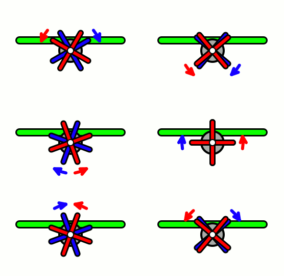
P-factor, also known as asymmetric blade effect and asymmetric disc effect, is an aerodynamic phenomenon experienced by a moving propeller,) where the propeller's center of thrust moves off-center when the aircraft is at a high angle of attack. This shift in the location of the center of thrust will exert a yawing moment on the aircraft, causing it to yaw slightly to one side. A rudder input is required to counteract the yawing tendency. Causes When a propeller aircraft is flying at cruise speed in level flight, the propeller disc is perpendicular to the relative airflow through the propeller. Each of the propeller blades contacts the air at the same angle and speed, and thus the thrust produced is evenly distributed across the propeller. However, at lower speeds the aircraft will typically be in a nose-high attitude, with the propeller disc rotated slightly toward the horizontal. This has two effects. Firstly, propeller blades will be more forward when in the down positi ... [...More Info...] [...Related Items...] OR: [Wikipedia] [Google] [Baidu] |
Fixed-wing Aircraft
A fixed-wing aircraft is a heavier-than-air flying machine, such as an airplane, which is capable of flight using wings that generate lift caused by the aircraft's forward airspeed and the shape of the wings. Fixed-wing aircraft are distinct from rotary-wing aircraft (in which the wings form a rotor mounted on a spinning shaft or "mast"), and ornithopters (in which the wings flap in a manner similar to that of a bird). The wings of a fixed-wing aircraft are not necessarily rigid; kites, hang gliders, variable-sweep wing aircraft and airplanes that use wing morphing are all examples of fixed-wing aircraft. Gliding fixed-wing aircraft, including free-flying gliders of various kinds and tethered kites, can use moving air to gain altitude. Powered fixed-wing aircraft (airplanes) that gain forward thrust from an engine include powered paragliders, powered hang gliders and some ground effect vehicles. Most fixed-wing aircraft are flown by a pilot on board the craft, but some ar ... [...More Info...] [...Related Items...] OR: [Wikipedia] [Google] [Baidu] |
Voith-Schneider
A cyclorotor, cycloidal rotor, cycloidal propeller or cyclogiro, is a fluid propulsion device that converts shaft power into the acceleration of a fluid using a rotating axis perpendicular to the direction of fluid motion. It uses several blades with a spanwise axis parallel to the axis of rotation and perpendicular to the direction of fluid motion. These blades are cyclically pitched twice per revolution to produce force (thrust or lift) in any direction normal to the axis of rotation. Cyclorotors are used for propulsion, lift, and control on air and water vehicles. An aircraft using cyclorotors as the primary source of lift, propulsion, and control is known as a cyclogyro or cyclocopter. A unique aspect is that it can change the magnitude and direction of thrust without the need of tilting any aircraft structures. The patented application, used on ships with particular actuation mechanisms both mechanical or hydraulic, is named after German company Voith Turbo. Operating princip ... [...More Info...] [...Related Items...] OR: [Wikipedia] [Google] [Baidu] |
Contra-rotating Propellers
Aircraft equipped with contra-rotating propellers, also referred to as CRP, coaxial contra-rotating propellers, or high-speed propellers, apply the maximum power of usually a single piston or turboprop engine to drive a pair of coaxial propellers in contra-rotation. Two propellers are arranged one behind the other, and power is transferred from the engine via a planetary gear or spur gear transmission. Contra-rotating propellers are also known as counter-rotating propellers, although counter-rotating propellers is much more widely used when referring to airscrews on separate non-coaxial shafts turning in opposite directions. Operation When airspeed is low, the mass of the air flowing through the propeller disk (thrust) causes a significant amount of tangential or rotational air flow to be created by the spinning blades. The energy of this tangential air flow is wasted in a single-propeller design, and causes handling problems at low speed as the air strikes the vertical st ... [...More Info...] [...Related Items...] OR: [Wikipedia] [Google] [Baidu] |
Counter-rotating Propellers
Counter-rotating propellers, also referred to as CRP, are propellers which spin in opposite directions to each other. They are used on some twin- and multi-engine propeller-driven aircraft. The propellers on most conventional twin-engined aircraft spin clockwise (as viewed from behind the engine). Counter-rotating propellers generally spin clockwise on the left engine and counter-clockwise on the right. The advantage of such designs is that counter-rotating propellers balance the effects of torque and P-factor, meaning that such aircraft do not have a critical engine in the case of engine failure. Drawbacks of counter-rotating propellers come from the fact that, in order to reverse the rotation of one propeller, either one propeller must have an additional reversing gearbox, or the engines themselves must be adapted to turn in opposite directions. (Meaning that there are essentially two engine designs, one with left-turning and the other with right-turning parts, which compl ... [...More Info...] [...Related Items...] OR: [Wikipedia] [Google] [Baidu] |
Cavitation
Cavitation is a phenomenon in which the static pressure of a liquid reduces to below the liquid's vapour pressure, leading to the formation of small vapor-filled cavities in the liquid. When subjected to higher pressure, these cavities, called "bubbles" or "voids", collapse and can generate shock waves that may damage machinery. These shock waves are strong when they are very close to the imploded bubble, but rapidly weaken as they propagate away from the implosion. Cavitation is a significant cause of wear in some engineering contexts. Collapsing voids that implode near to a metal surface cause cyclic stress through repeated implosion. This results in surface fatigue of the metal causing a type of wear also called "cavitation". The most common examples of this kind of wear are to pump impellers, and bends where a sudden change in the direction of liquid occurs. Cavitation is usually divided into two classes of behavior: inertial (or transient) cavitation and non-inertial c ... [...More Info...] [...Related Items...] OR: [Wikipedia] [Google] [Baidu] |

