|
Physical Layout
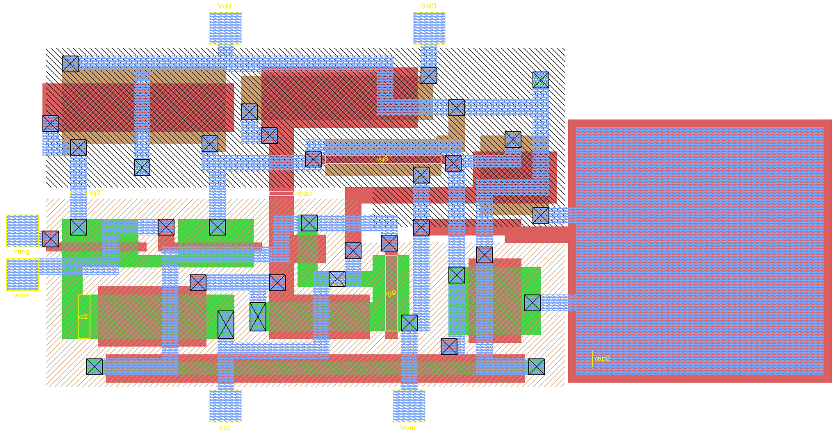
Integrated circuit layout, also known IC layout, IC mask layout, or mask design, is the representation of an integrated circuit in terms of planar geometric shapes which correspond to the patterns of metal, oxide, or semiconductor layers that make up the components of the integrated circuit. Originally the overall process was called tapeout as historically early ICs used graphical black crepe tape on mylar media for photo imaging (erroneously believed to reference magnetic data—the photo process greatly predated magnetic media). When using a standard process—where the interaction of the many chemical, thermal, and photographic variables is known and carefully controlled—the behaviour of the final integrated circuit depends largely on the positions and interconnections of the geometric shapes. Using a computer-aided layout tool, the layout engineer—or layout technician—places and connects all of the components that make up the chip such that they meet certain criteria— ... [...More Info...] [...Related Items...] OR: [Wikipedia] [Google] [Baidu] |
Printed Circuit Board
A printed circuit board (PCB; also printed wiring board or PWB) is a medium used in Electrical engineering, electrical and electronic engineering to connect electronic components to one another in a controlled manner. It takes the form of a Lamination, laminated sandwich structure of conductive and insulating layers: each of the conductive layers is designed with an artwork pattern of traces, planes and other features (similar to wires on a flat surface) Chemical milling, etched from one or more sheet layers of copper Lamination, laminated onto and/or between sheet layers of a Insulator (electricity), non-conductive substrate. Electrical components may be fixed to conductive pads on the outer layers in the shape designed to accept the component's terminals, generally by means of soldering, to both electrically connect and mechanically fasten them to it. Another manufacturing process adds Via (electronics), vias: plated-through holes that allow interconnections between layers. ... [...More Info...] [...Related Items...] OR: [Wikipedia] [Google] [Baidu] |
Electronic Design
''Electronic Design'' magazine, founded in 1952, is an electronics and electrical engineering trade magazine and website. History Hayden Publishing Company began publishing the bi-weekly magazine Electronic Design in December 1952, and was later published by InformaUSA, Inc. In 1986, Verenigde Nederlandse Uitgeverijen, purchased Hayden Publishing Inc. In June 1988, Verenigde Nederlandse Uitgeverijen, purchased ''Electronic Design'' from McGraw-Hill. In July 1989, Penton Media, purchased ''Electronic Design'', then in Hasbrouck, N.J., from Verenigde Nederlandse Uitgeverijen. In July 2007, Penton Media's OEM electronics publication, ''EE Product News'', merged with Penton Media's "Electronic Design" magazine. ''EE Product News'' was founded in 1941, as a monthly publication. In September 2016, Informa, purchased Penton Media, including ''Electronic Design''. In November 2019, Endeavor Business Media purchased ''Electronic Design'' from Informa. Content Sections i ... [...More Info...] [...Related Items...] OR: [Wikipedia] [Google] [Baidu] |
Floorplan (microelectronics)
In electronic design automation, a floorplan of an integrated circuit is a schematics representation of tentative placement of its major functional blocks. In modern electronic design process floorplans are created during the floorplanning design stage, an early stage in the hierarchical approach to integrated circuit design. Depending on the design methodology being followed, the actual definition of a floorplan may differ. Floorplanning Floorplanning takes in some of the geometrical constraints in a design. Here are some examples: * bonding pads for off-chip connections (often using wire bonding) are normally located at the circumference of the chip; * line drivers often have to be located as close to bonding pads as possible; * chip area is therefore in some cases given a minimum area in order to fit in the required number of pads; * areas are clustered in order to limit data paths thus frequently featuring defined structures such as cache RAM, multiplier, barrel shifter, ... [...More Info...] [...Related Items...] OR: [Wikipedia] [Google] [Baidu] |
Integrated Circuit Design
Integrated circuit design, or IC design, is a sub-field of electronics engineering, encompassing the particular logic and circuit design techniques required to design integrated circuits, or ICs. ICs consist of miniaturized electronic components built into an electrical network on a monolithic semiconductor substrate by photolithography. IC design can be divided into the broad categories of digital and analog IC design. Digital IC design is to produce components such as microprocessors, FPGAs, memories (RAM, ROM, and flash) and digital ASICs. Digital design focuses on logical correctness, maximizing circuit density, and placing circuits so that clock and timing signals are routed efficiently. Analog IC design also has specializations in power IC design and RF IC design. Analog IC design is used in the design of op-amps, linear regulators, phase locked loops, oscillators and active filters. Analog design is more concerned with the physics of the semiconductor devices such as ... [...More Info...] [...Related Items...] OR: [Wikipedia] [Google] [Baidu] |
Printed Circuit Board
A printed circuit board (PCB; also printed wiring board or PWB) is a medium used in Electrical engineering, electrical and electronic engineering to connect electronic components to one another in a controlled manner. It takes the form of a Lamination, laminated sandwich structure of conductive and insulating layers: each of the conductive layers is designed with an artwork pattern of traces, planes and other features (similar to wires on a flat surface) Chemical milling, etched from one or more sheet layers of copper Lamination, laminated onto and/or between sheet layers of a Insulator (electricity), non-conductive substrate. Electrical components may be fixed to conductive pads on the outer layers in the shape designed to accept the component's terminals, generally by means of soldering, to both electrically connect and mechanically fasten them to it. Another manufacturing process adds Via (electronics), vias: plated-through holes that allow interconnections between layers. ... [...More Info...] [...Related Items...] OR: [Wikipedia] [Google] [Baidu] |
Physical Design (electronics)
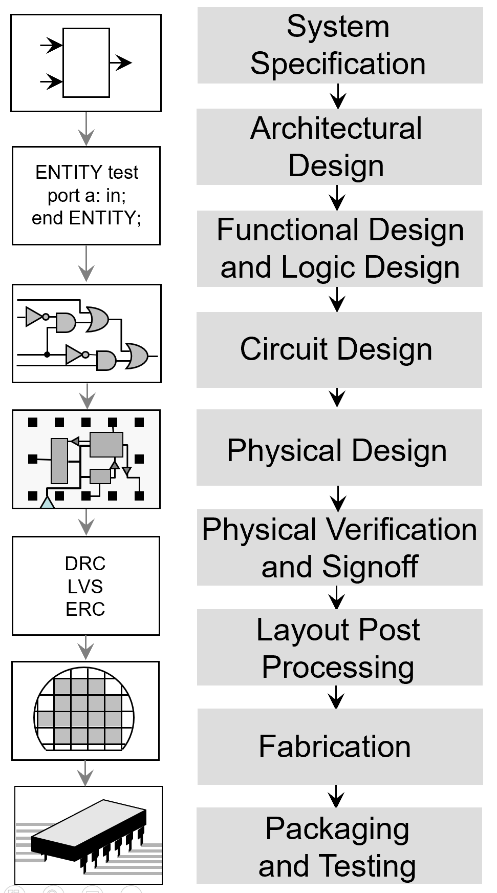
In integrated circuit design, physical design is a step in the standard design cycle which follows after the circuit design. At this step, circuit representations of the components (devices and interconnects) of the design are converted into geometric representations of shapes which, when manufactured in the corresponding layers of materials, will ensure the required functioning of the components. This geometric representation is called integrated circuit layout. This step is usually split into several sub-steps, which include both design and verification and validation of the layout. Modern day Integrated Circuit (IC) design is split up into ''Front-end Design using HDLs'' and ''Back-end Design'' or ''Physical Design''. The inputs to physical design are (i) a netlist, (ii) library information on the basic devices in the design, and (iii) a technology file containing the manufacturing constraints. Physical design is usually concluded by ''Layout Post Processing'', in which amendmen ... [...More Info...] [...Related Items...] OR: [Wikipedia] [Google] [Baidu] |
Interconnects (integrated Circuits)
In integrated circuits (ICs), interconnects are structures that connect two or more circuit elements (such as transistors) together electrically. The design and layout of interconnects on an IC is vital to its proper function, performance, power efficiency, reliability, and fabrication yield. The material interconnects are made from depends on many factors. Chemical and mechanical compatibility with the semiconductor substrate and the dielectric between the levels of interconnect is necessary, otherwise barrier layers are needed. Suitability for fabrication is also required; some chemistries and processes prevent the integration of materials and unit processes into a larger technology (recipe) for IC fabrication. In fabrication, interconnects are formed during the back-end-of-line after the fabrication of the transistors on the substrate. Interconnects are classified as ''local'' or ''global'' interconnects depending on the signal propagation distance it is able to support. The wid ... [...More Info...] [...Related Items...] OR: [Wikipedia] [Google] [Baidu] |
Polygon
In geometry, a polygon () is a plane figure that is described by a finite number of straight line segments connected to form a closed ''polygonal chain'' (or ''polygonal circuit''). The bounded plane region, the bounding circuit, or the two together, may be called a polygon. The segments of a polygonal circuit are called its '' edges'' or ''sides''. The points where two edges meet are the polygon's '' vertices'' (singular: vertex) or ''corners''. The interior of a solid polygon is sometimes called its ''body''. An ''n''-gon is a polygon with ''n'' sides; for example, a triangle is a 3-gon. A simple polygon is one which does not intersect itself. Mathematicians are often concerned only with the bounding polygonal chains of simple polygons and they often define a polygon accordingly. A polygonal boundary may be allowed to cross over itself, creating star polygons and other self-intersecting polygons. A polygon is a 2-dimensional example of the more general polytope in any number ... [...More Info...] [...Related Items...] OR: [Wikipedia] [Google] [Baidu] |
Standard Cell
In semiconductor design, standard cell methodology is a method of designing application-specific integrated circuits (ASICs) with mostly digital-logic features. Standard cell methodology is an example of design abstraction, whereby a low-level very-large-scale integration (VLSI) layout is encapsulated into an abstract logic representation (such as a NAND gate). Cell-based methodology — the general class to which standard cells belong — makes it possible for one designer to focus on the high-level (logical function) aspect of digital design, while another designer focuses on the implementation (physical) aspect. Along with semiconductor manufacturing advances, standard cell methodology has helped designers scale ASICs from comparatively simple single-function ICs (of several thousand gates), to complex multi-million gate system-on-a-chip (SoC) devices. Construction of a standard cell A standard cell is a group of transistor and interconnect structures that provides a boolean ... [...More Info...] [...Related Items...] OR: [Wikipedia] [Google] [Baidu] |
Schematic-driven Layout
Schematic driven layout is the concept in integrated circuit layout or PCB PCB may refer to: Science and technology * Polychlorinated biphenyl, an organic chlorine compound, now recognized as an environmental toxin and classified as a persistent organic pollutant * Printed circuit board, a board used in electronics * ... layout where the EDA software links the schematic and layout databases. It was one of the first big steps forward in layout software from the days when editing tools were simply handling drawn polygons. Features Schematic-driven layout allows for several features that make the layout designer's job easier and faster. One of the most important is that changes to the circuit schematic are easily translated to the layout. Another is that the connections between components in the schematic are graphically displayed in the layout ensuring work is correct by construction. References * Clein, Dan. (2000). ''CMOS IC Layout''. Newnes. {{ISBN, 0-7506-7194-7 El ... [...More Info...] [...Related Items...] OR: [Wikipedia] [Google] [Baidu] |
Place And Route
Place and route is a stage in the design of printed circuit boards, integrated circuits, and field-programmable gate arrays. As implied by the name, it is composed of two steps, placement and routing. The first step, placement, involves deciding where to place all electronic components, circuitry, and logic elements in a generally limited amount of space. This is followed by routing, which decides the exact design of all the wires needed to connect the placed components. This step must implement all the desired connections while following the rules and limitations of the manufacturing process. Place and route is used in several contexts: * Printed circuit boards, during which components are graphically placed on the board and the wires drawn between them * Integrated circuits, during which a layout of a larger block of the circuit or the whole circuit is created from layouts of smaller sub-blocks * FPGAs, during which logic elements are placed and interconnected on the grid of the ... [...More Info...] [...Related Items...] OR: [Wikipedia] [Google] [Baidu] |


