|
Omnidirectional Antenna
In radio communication, an omnidirectional antenna is a class of antenna which radiates equal radio power in all directions perpendicular to an axis (azimuthal directions), with power varying with angle to the axis ( elevation angle), declining to zero on the axis. When graphed in three dimensions ''(see graph)'' this radiation pattern is often described as ''doughnut-shaped''. Note that this is different from an isotropic antenna, which radiates equal power in ''all'' directions, having a ''spherical'' radiation pattern. Omnidirectional antennas oriented vertically are widely used for nondirectional antennas on the surface of the Earth because they radiate equally in all horizontal directions, while the power radiated drops off with elevation angle so little radio energy is aimed into the sky or down toward the earth and wasted. Omnidirectional antennas are widely used for radio broadcasting antennas, and in mobile devices that use radio such as cell phones, FM radios, wa ... [...More Info...] [...Related Items...] OR: [Wikipedia] [Google] [Baidu] |
Radio Waves
Radio waves are a type of electromagnetic radiation with the longest wavelengths in the electromagnetic spectrum, typically with frequencies of 300 gigahertz ( GHz) and below. At 300 GHz, the corresponding wavelength is 1 mm (shorter than a grain of rice); at 30 Hz the corresponding wavelength is (longer than the radius of the Earth). Like all electromagnetic waves, radio waves in a vacuum travel at the speed of light, and in the Earth's atmosphere at a close, but slightly lower speed. Radio waves are generated by charged particles undergoing acceleration, such as time-varying electric currents. Naturally occurring radio waves are emitted by lightning and astronomical objects, and are part of the blackbody radiation emitted by all warm objects. Radio waves are generated artificially by an electronic device called a transmitter, which is connected to an antenna which radiates the waves. They are received by another antenna connected to a radio receiv ... [...More Info...] [...Related Items...] OR: [Wikipedia] [Google] [Baidu] |
Collinear
In geometry, collinearity of a set of points is the property of their lying on a single line. A set of points with this property is said to be collinear (sometimes spelled as colinear). In greater generality, the term has been used for aligned objects, that is, things being "in a line" or "in a row". Points on a line In any geometry, the set of points on a line are said to be collinear. In Euclidean geometry this relation is intuitively visualized by points lying in a row on a "straight line". However, in most geometries (including Euclidean) a line is typically a primitive (undefined) object type, so such visualizations will not necessarily be appropriate. A model for the geometry offers an interpretation of how the points, lines and other object types relate to one another and a notion such as collinearity must be interpreted within the context of that model. For instance, in spherical geometry, where lines are represented in the standard model by great circles of a sphere, ... [...More Info...] [...Related Items...] OR: [Wikipedia] [Google] [Baidu] |
Collinear Antenna Array
In telecommunications, a collinear antenna array (sometimes colinear antenna array) is an array of dipole or quarter-wave antennas mounted in such a manner that the corresponding elements of each antenna are parallel and collinear; that is, they are located along a common axis. Collinear arrays are high gain omnidirectional antennas. Both dipoles and quarter-wavelength monopoles have an omnidirectional radiation pattern in free space when oriented vertically; they radiate equal radio power in all azimuthal directions perpendicular to the antenna, with the signal strength dropping to zero on the antenna axis. The purpose of stacking multiple antennas in a vertical collinear array is to increase the power radiated in horizontal directions and reduce the power radiated into the sky or down toward the earth, where it is wasted. They radiate vertically polarized radio waves. Theoretically, when stacking idealized lossless antennas in such a fashion, doubling their number wil ... [...More Info...] [...Related Items...] OR: [Wikipedia] [Google] [Baidu] |
Halo Antenna
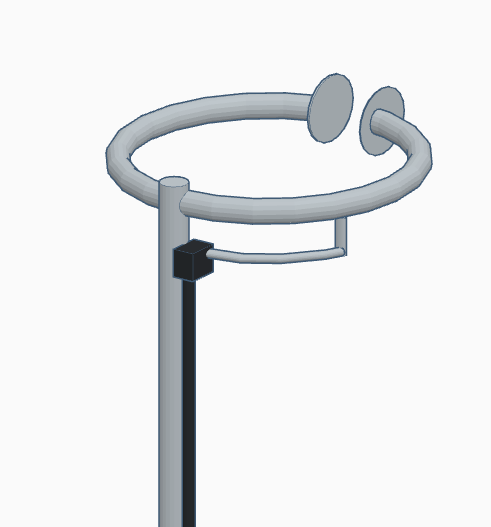
A halo antenna, or halo, is a center-fed dipole antenna, which has been bent into a circle, with a break directly opposite the feed point. The dipole ends are close, but do not touch, and may be widened to form an air capacitor, whose spacing is used to adjust the antenna's resonant frequency. Most often mounted horizontally, this antenna's radiation is then approximately omnidirectional and horizontally polarized. Halo antennas vs. loop antennas This section contrasts halo antennas with loop antennas which are electrically dissimilar, but can be confused as they all share the same circular shape. Halo vs. large loops Although also a resonant antenna, the halo antenna is distinct from the full-wave loop antenna, which is approximately double its size for the same operating frequency. In the case of the halo antenna, each half is about a quarter wavelength long and ends with a current node (zero current and peak voltage) at the break. On the other hand, the two semi-circles of ... [...More Info...] [...Related Items...] OR: [Wikipedia] [Google] [Baidu] |
Loop Antenna
A loop antenna is a radio antenna consisting of a loop or coil of wire, tubing, or other electrical conductor, that is usually fed by a balanced source or feeding a balanced load. Within this physical description there are two (possibly three) distinct types: * Large loop antennas (or ''self-resonant loop antennas'') have a perimeter close to one or more whole wavelengths at the operating frequency, which makes them self-resonant at that frequency. They are the most efficient of all antenna types for both transmission and reception. Large loop antennas have a two-lobe radiation pattern at their first, full-wave resonance, peaking in both directions ''perpendicular'' to the plane of the loop. * Halo antennas are shortened dipoles that have been bent into a circular loop, with the ends not quite touching. Some writers prefer to exclude them from loop antennas, since they can be well-understood as bent dipoles, others make halos an intermediate category between large and small l ... [...More Info...] [...Related Items...] OR: [Wikipedia] [Google] [Baidu] |
Mast Radiator
Mast, MAST or MASt may refer to: Engineering * Mast (sailing), a vertical spar on a sailing ship * Flagmast, a pole for flying a flag * Guyed mast, a structure supported by guy-wires * Mooring mast, a structure for docking an airship * Radio masts and towers , towers that carry antennas * The primary support for a helicopter rotor * The main vertical structure of a forklift truck * Multi-axis shaker table, an automotive test system * Model for assessment of telemedicine, used to assess long-distance medical treatment Biology * Mast (botany), the edible parts of woody plants * Mast Arboretum, at Stephen F. Austin State University in Nacogdoches, Texas * Mast cell, involved in the allergy response * Mast., in botanical naming, the standard author abbreviation for Maxwell T. Masters * Two microtubule-associated serine/threonine-protein kinase enzymes: ** MAST1, an enzyme that in humans is encoded by the ''MAST1'' gene ** MAST2, an enzyme that in humans is encoded by the ''MAST2 ... [...More Info...] [...Related Items...] OR: [Wikipedia] [Google] [Baidu] |
Discone Antenna
A discone antenna is a version of a biconical antenna in which one of the cones is replaced by a disc. It is usually mounted vertically, with the disc at the top and the cone beneath. Omnidirectional, vertically polarized and with gain similar to a dipole, it is exceptionally wideband, offering a frequency range ratio of up to approximately 10:1. The radiation pattern in the vertical plane is quite narrow, making its sensitivity highest in the direction of the horizon and rather less for signals coming from relatively close by. History On February 6, 1945, Armig G. Kandoian of New York City was awarded U.S. patent number (assignor to Federal Telephone and Radio Corporation, later merged with ITT Corporation), from an application made on May 15, 1943. Excerpt from the Kandoian patent: In keeping with progress made during the last few years in the development of ultra-high frequency radio technique, and applications thereof to aircraft communication, direction finding, ... [...More Info...] [...Related Items...] OR: [Wikipedia] [Google] [Baidu] |
Monopole Antenna
A monopole antenna is a class of radio antenna consisting of a straight rod-shaped conductor, often mounted perpendicularly over some type of conductive surface, called a ground plane. The driving signal from the transmitter is applied, or for receiving antennas the output signal to the receiver is taken, between the lower end of the monopole and the ground plane. One side of the antenna feedline is attached to the lower end of the monopole, and the other side is attached to the ground plane, which is often the Earth. This contrasts with a dipole antenna which consists of two identical rod conductors, with the signal from the transmitter applied between the two halves of the antenna. The monopole is often used as a resonant antenna; the rod functions as an open resonator for radio waves, oscillating with standing waves of voltage and current along its length. Therefore the length of the antenna is determined by the wavelength of the radio waves it is used with. The most ... [...More Info...] [...Related Items...] OR: [Wikipedia] [Google] [Baidu] |
Rubber Ducky Antenna
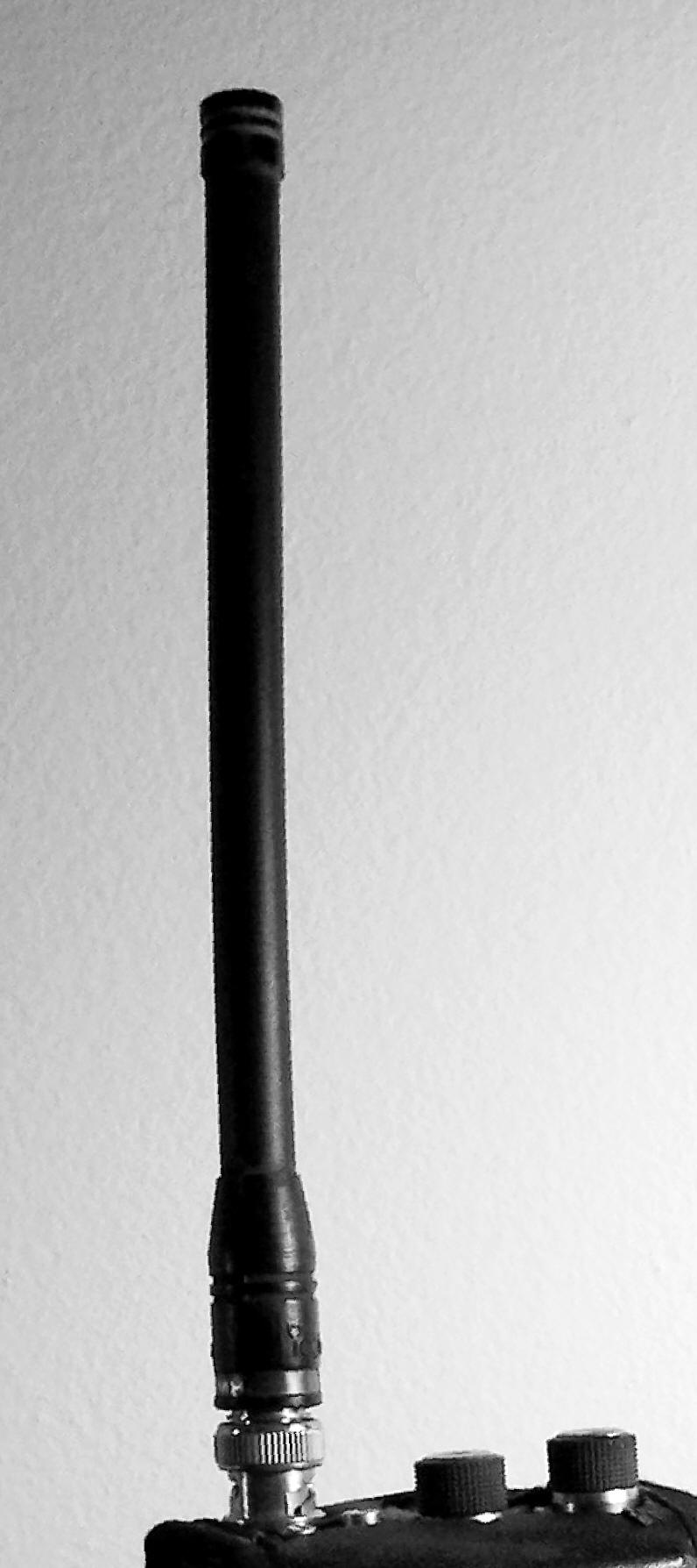
The rubber ducky antenna (or rubber duck aerial) is an electrically short monopole antenna that functions somewhat like a base-loaded whip antenna. It consists of a springy wire in the shape of a narrow helix, sealed in a rubber or plastic jacket to protect the antenna.. A note at the bottom of the page says this page is not copyrighted, and text from this page has been quoted verbatim in this article Rubber ducky antenna is a form of normal-mode helical antenna. Electrically short antennas like the rubber ducky are used in portable handheld radio equipment at VHF and UHF frequencies in place of a quarter wavelength whip antenna, which is inconveniently long and cumbersome at these frequencies. Many years after its invention in 1958, the rubber ducky antenna became the antenna of choice for many portable radio devices, including walkie-talkies and other portable transceivers, scanners and other devices where safety and robustness take precedence over electromagnetic perf ... [...More Info...] [...Related Items...] OR: [Wikipedia] [Google] [Baidu] |
Whip Antenna
A whip antenna is an antenna consisting of a straight flexible wire or rod. The bottom end of the whip is connected to the radio receiver or transmitter. A whip antenna is a form of monopole antenna. The antenna is designed to be flexible so that it does not break easily, and the name is derived from the whip-like motion that it exhibits when disturbed. Whip antennas for portable radios are often made of a series of interlocking telescoping metal tubes, so they can be retracted when not in use. Longer whips, made for mounting on vehicles and structures, are made of a flexible fiberglass rod around a wire core and can be up to long. The ideal length of the whip antenna is determined by the wavelength of the radio waves it is used with. The most common type is the ''quarter-wave whip'', which is approximately long, but they can be either longer or shorter by design, varying from compact electrically short antennas wavelength long, up to wavelength to improve di ... [...More Info...] [...Related Items...] OR: [Wikipedia] [Google] [Baidu] |
Ground Plane
In electrical engineering, a ground plane is an electrically conductive surface, usually connected to electrical ground. The term has two different meanings in separate areas of electrical engineering. *In antenna theory, a ground plane is a conducting surface large in comparison to the wavelength, such as the Earth, which is connected to the transmitter's ground wire and serves as a reflecting surface for radio waves. *In printed circuit boards, a ground plane is a large area of copper foil on the board which is connected to the power supply ground terminal and serves as a return path for current from different components on the board. Radio antenna theory In telecommunication, a ''ground plane'' is a flat or nearly flat horizontal conducting surface that serves as part of an antenna, to reflect the radio waves from the other antenna elements. The plane does not necessarily have to be connected to ground to be used as a reflecting surface for radio waves. Ground plane shap ... [...More Info...] [...Related Items...] OR: [Wikipedia] [Google] [Baidu] |


