|
Null (physics)
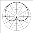
In physics a null is a point in a field where the field quantity is zero as the result of two or more opposing quantities completely cancelling each other. The field may be scalar, vector or tensor in nature. Common situations where nulls arise are in the polar patterns of microphones and antennae, and nulls caused by reflections of waves. Microphones A common polar pattern for microphones is the cardioid. This has a single direction in which the microphone does not respond to impinging sound waves. Highly directional (shotgun) microphones have more complex polar patterns. These microphones have a large, narrow lobe in the main direction of sound reception but also a smaller lobe in the opposite direction and usually also several other smaller lobes. This pattern is achieved by wave cancellation inside the body of the microphone. Between each of these lobes is a null direction where no sound at all is detected. Antennae {{main, null (radio) A common, and basic, radio ant ... [...More Info...] [...Related Items...] OR: [Wikipedia] [Google] [Baidu] |
Field (physics)
In physics, a field is a physical quantity, represented by a scalar (mathematics), scalar, vector (mathematics and physics), vector, or tensor, that has a value for each Point (geometry), point in Spacetime, space and time. For example, on a weather map, the surface temperature is described by assigning a real number, number to each point on the map; the temperature can be considered at a certain point in time or over some interval of time, to study the dynamics of temperature change. A surface wind map, assigning an vector (mathematics and physics), arrow to each point on a map that describes the wind velocity, speed and direction at that point, is an example of a vector field, i.e. a 1-dimensional (rank-1) tensor field. Field theories, mathematical descriptions of how field values change in space and time, are ubiquitous in physics. For instance, the electric field is another rank-1 tensor field, while electrodynamics can be formulated in terms of Mathematical descriptions of the ... [...More Info...] [...Related Items...] OR: [Wikipedia] [Google] [Baidu] |
Standing Wave Nulls
Standing, also referred to as orthostasis, is a position in which the body is held in an ''erect'' ("orthostatic") position and supported only by the feet. Although seemingly static, the body rocks slightly back and forth from the ankle in the sagittal plane. The sagittal plane bisects the body into right and left sides. The sway of quiet standing is often likened to the motion of an inverted pendulum. Standing at attention is a military standing posture, as is stand at ease, but these terms are also used in military-style organisations and in some professions which involve standing, such as modeling. ''At ease'' refers to the classic military position of standing with legs slightly apart, not in as formal or regimented a pose as standing at attention. In modeling, ''model at ease'' refers to the model standing with one leg straight, with the majority of the weight on it, and the other leg tucked over and slightly around. Control Standing posture relies on dynamic rather than st ... [...More Info...] [...Related Items...] OR: [Wikipedia] [Google] [Baidu] |
VSWR
In radio engineering and telecommunications, standing wave ratio (SWR) is a measure of impedance matching of loads to the characteristic impedance of a transmission line or waveguide. Impedance mismatches result in standing waves along the transmission line, and SWR is defined as the ratio of the partial standing wave's amplitude at an antinode (maximum) to the amplitude at a node (minimum) along the line. The SWR is usually thought of in terms of the maximum and minimum AC voltages along the transmission line, thus called the voltage standing wave ratio or VSWR (sometimes pronounced "vizwar" ). For example, the VSWR value 1.2:1 means that an AC voltage, due to standing waves along the transmission line, will have a peak value 1.2 times that of the minimum AC voltage along that line, if the line is at least one half wavelength long. The SWR can be also defined as the ratio of the maximum amplitude to minimum amplitude of the transmission line's currents, electric field strength, ... [...More Info...] [...Related Items...] OR: [Wikipedia] [Google] [Baidu] |
Slotted Line
Slotted lines are used for microwave measurements and consist of a movable probe inserted into a slot in a transmission line. They are used in conjunction with a microwave power source and usually, in keeping with their low-cost application, a low cost Schottky diode detector and VSWR meter rather than an expensive microwave power meter. Slotted lines can measure standing waves, wavelength, and, with some calculation or plotting on Smith charts, a number of other parameters including reflection coefficient and electrical impedance. A precision variable attenuator is often incorporated in the test setup to improve accuracy. This is used to make level measurements, while the detector and VSWR meter are retained only to mark a reference point for the attenuator to be set to, thus eliminating entirely the detector and meter measurement errors. The parameter most commonly measured by a slotted line is SWR. This serves as a measure of the accuracy of the impedance match to the it ... [...More Info...] [...Related Items...] OR: [Wikipedia] [Google] [Baidu] |
Electrical Impedance
In electrical engineering, impedance is the opposition to alternating current presented by the combined effect of resistance and reactance in a circuit. Quantitatively, the impedance of a two-terminal circuit element is the ratio of the complex representation of the sinusoidal voltage between its terminals, to the complex representation of the current flowing through it. In general, it depends upon the frequency of the sinusoidal voltage. Impedance extends the concept of resistance to alternating current (AC) circuits, and possesses both magnitude and phase, unlike resistance, which has only magnitude. Impedance can be represented as a complex number, with the same units as resistance, for which the SI unit is the ohm (). Its symbol is usually , and it may be represented by writing its magnitude and phase in the polar form . However, Cartesian complex number representation is often more powerful for circuit analysis purposes. The notion of impedance is useful for perf ... [...More Info...] [...Related Items...] OR: [Wikipedia] [Google] [Baidu] |
Wavelength
In physics, the wavelength is the spatial period of a periodic wave—the distance over which the wave's shape repeats. It is the distance between consecutive corresponding points of the same phase on the wave, such as two adjacent crests, troughs, or zero crossings, and is a characteristic of both traveling waves and standing waves, as well as other spatial wave patterns. The inverse of the wavelength is called the spatial frequency. Wavelength is commonly designated by the Greek letter ''lambda'' (λ). The term ''wavelength'' is also sometimes applied to modulated waves, and to the sinusoidal envelopes of modulated waves or waves formed by interference of several sinusoids. Assuming a sinusoidal wave moving at a fixed wave speed, wavelength is inversely proportional to frequency of the wave: waves with higher frequencies have shorter wavelengths, and lower frequencies have longer wavelengths. Wavelength depends on the medium (for example, vacuum, air, or water) that a wav ... [...More Info...] [...Related Items...] OR: [Wikipedia] [Google] [Baidu] |
Reflections Of Signals On Conducting Lines
A signal travelling along an electrical transmission line will be partly, or wholly, reflected back in the opposite direction when the travelling signal encounters a discontinuity in the characteristic impedance of the line, or if the far end of the line is not terminated in its characteristic impedance. This can happen, for instance, if two lengths of dissimilar transmission lines are joined. This article is about signal reflections on electrically conducting lines. Such lines are loosely referred to as copper lines, and indeed, in telecommunications are generally made from copper, but other metals are used, notably aluminium in power lines. Although this article is limited to describing reflections on conducting lines, this is essentially the same phenomenon as optical reflections in fibre-optic lines and microwave reflections in waveguides. Reflections cause several undesirable effects, including modifying frequency responses, causing overload power in transmitters and ov ... [...More Info...] [...Related Items...] OR: [Wikipedia] [Google] [Baidu] |
Electrical Resistance
The electrical resistance of an object is a measure of its opposition to the flow of electric current. Its reciprocal quantity is , measuring the ease with which an electric current passes. Electrical resistance shares some conceptual parallels with mechanical friction. The SI unit of electrical resistance is the ohm (), while electrical conductance is measured in siemens (S) (formerly called the 'mho' and then represented by ). The resistance of an object depends in large part on the material it is made of. Objects made of electrical insulators like rubber tend to have very high resistance and low conductance, while objects made of electrical conductors like metals tend to have very low resistance and high conductance. This relationship is quantified by resistivity or conductivity. The nature of a material is not the only factor in resistance and conductance, however; it also depends on the size and shape of an object because these properties are extensive rather than intens ... [...More Info...] [...Related Items...] OR: [Wikipedia] [Google] [Baidu] |
Transmission Line
In electrical engineering, a transmission line is a specialized cable or other structure designed to conduct electromagnetic waves in a contained manner. The term applies when the conductors are long enough that the wave nature of the transmission must be taken into account. This applies especially to radio-frequency engineering because the short wavelengths mean that wave phenomena arise over very short distances (this can be as short as millimetres depending on frequency). However, the theory of transmission lines was historically developed to explain phenomena on very long telegraph lines, especially submarine telegraph cables. Transmission lines are used for purposes such as connecting radio transmitters and receivers with their antennas (they are then called feed lines or feeders), distributing cable television signals, trunklines routing calls between telephone switching centres, computer network connections and high speed computer data buses. RF engineers commonly ... [...More Info...] [...Related Items...] OR: [Wikipedia] [Google] [Baidu] |
Vibration Mode
A normal mode of a dynamical system is a pattern of motion in which all parts of the system move sinusoidally with the same frequency and with a fixed phase relation. The free motion described by the normal modes takes place at fixed frequencies. These fixed frequencies of the normal modes of a system are known as its natural frequency, natural frequencies or Resonance, resonant frequencies. A physical object, such as a building, bridge, or molecule, has a set of normal modes and their natural frequencies that depend on its structure, materials and boundary conditions. The most general motion of a system is a Superposition principle, superposition of its normal modes. The modes are normal in the sense that they can move independently, that is to say that an excitation of one mode will never cause motion of a different mode. In mathematical terms, normal modes are Orthogonality, orthogonal to each other. General definitions Mode In the Wave, wave theory of physics and ... [...More Info...] [...Related Items...] OR: [Wikipedia] [Google] [Baidu] |
Standing Wave
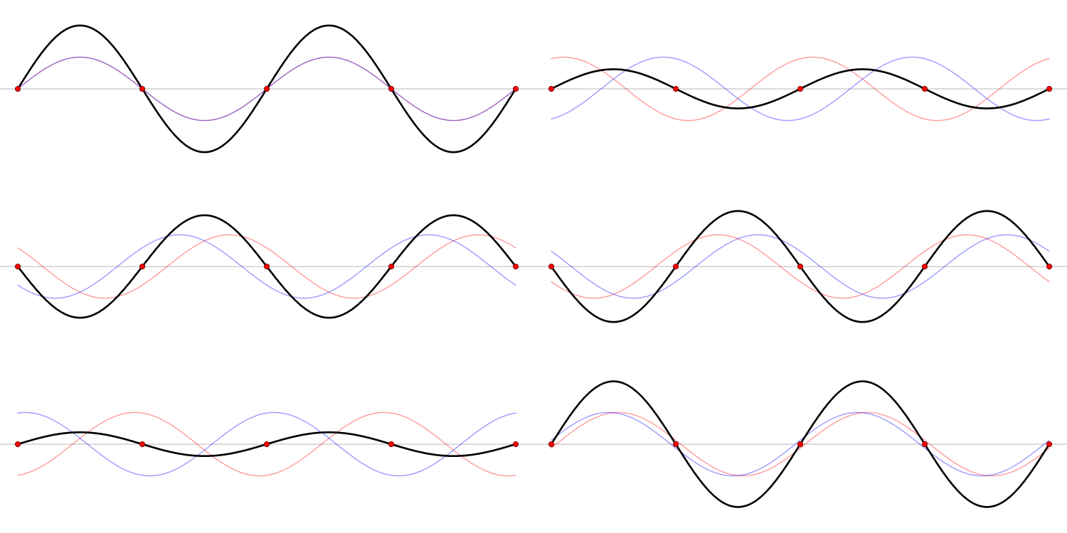
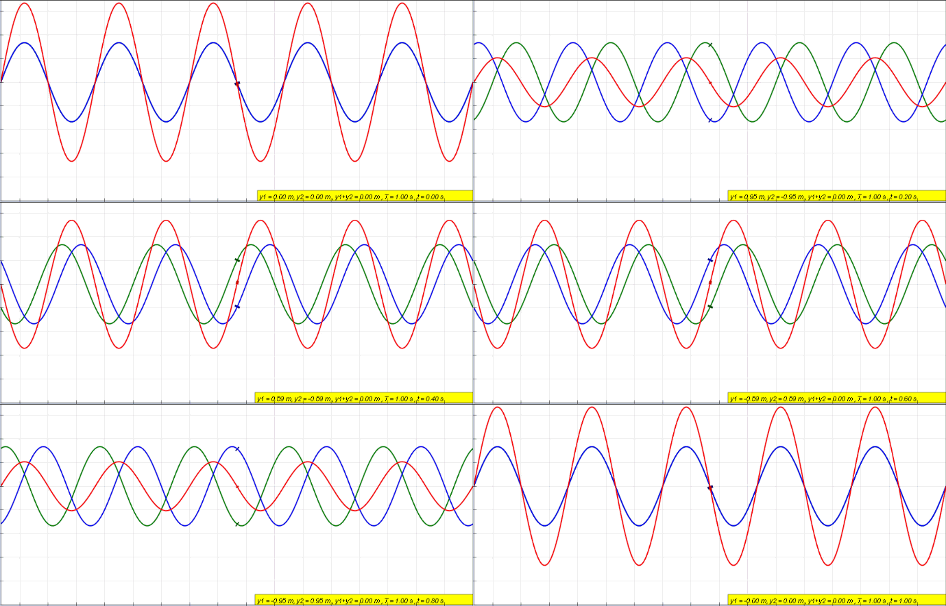
In physics, a standing wave, also known as a stationary wave, is a wave that oscillates in time but whose peak amplitude profile does not move in space. The peak amplitude of the wave oscillations at any point in space is constant with respect to time, and the oscillations at different points throughout the wave are in phase. The locations at which the absolute value of the amplitude is minimum are called nodes, and the locations where the absolute value of the amplitude is maximum are called antinodes. Standing waves were first noticed by Michael Faraday in 1831. Faraday observed standing waves on the surface of a liquid in a vibrating container. Franz Melde coined the term "standing wave" (German: ''stehende Welle'' or ''Stehwelle'') around 1860 and demonstrated the phenomenon in his classic experiment with vibrating strings. This phenomenon can occur because the medium is moving in the direction opposite to the movement of the wave, or it can arise in a stationary medium ... [...More Info...] [...Related Items...] OR: [Wikipedia] [Google] [Baidu] |


