|
ISO 128
ISO 128 is an international standard (ISO), about the general principles of presentation in technical drawings, specifically the graphical representation of objects on technical drawings.ISO 128-1:2003 Abstract Accessed 1 March 2009. Overview Since 2003 the ISO 128 standard contains fifteen parts, which were initiated between 1996 and 2003. It starts with a summary of the general rules for the execution and structure of technical drawings. Further it describes basic conventions for s, s, cuts and < ...[...More Info...] [...Related Items...] OR: [Wikipedia] [Google] [Baidu] |
International Organization For Standardization
The International Organization for Standardization (ISO ) is an international standard development organization composed of representatives from the national standards organizations of member countries. Membership requirements are given in Article 3 of the ISO Statutes. ISO was founded on 23 February 1947, and (as of November 2022) it has published over 24,500 international standards covering almost all aspects of technology and manufacturing. It has 809 Technical committees and sub committees to take care of standards development. The organization develops and publishes standardization in all technical and nontechnical fields other than electrical and electronic engineering, which is handled by the IEC.Editors of Encyclopedia Britannica. 3 June 2021.International Organization for Standardization" ''Encyclopedia Britannica''. Retrieved 2022-04-26. It is headquartered in Geneva, Switzerland, and works in 167 countries . The three official languages of the ISO are English, F ... [...More Info...] [...Related Items...] OR: [Wikipedia] [Google] [Baidu] |
Mechanical Engineering Drawing
{{Technical drawingsMechanical systems drawing is a type of technical drawing that shows information about heating, ventilating, air conditioning and transportation around the building (Elevators or Lifts and Escalator)."Building in Canada. The Requirements before Any Construction Project Begins" '''', Retrieved on 2011-01-29. It is a powerful tool that helps analyze complex systems. These drawings are often a set of detailed drawings used for construction projects; it is a requirement for all work. They ... [...More Info...] [...Related Items...] OR: [Wikipedia] [Google] [Baidu] |
Orthographic Representation
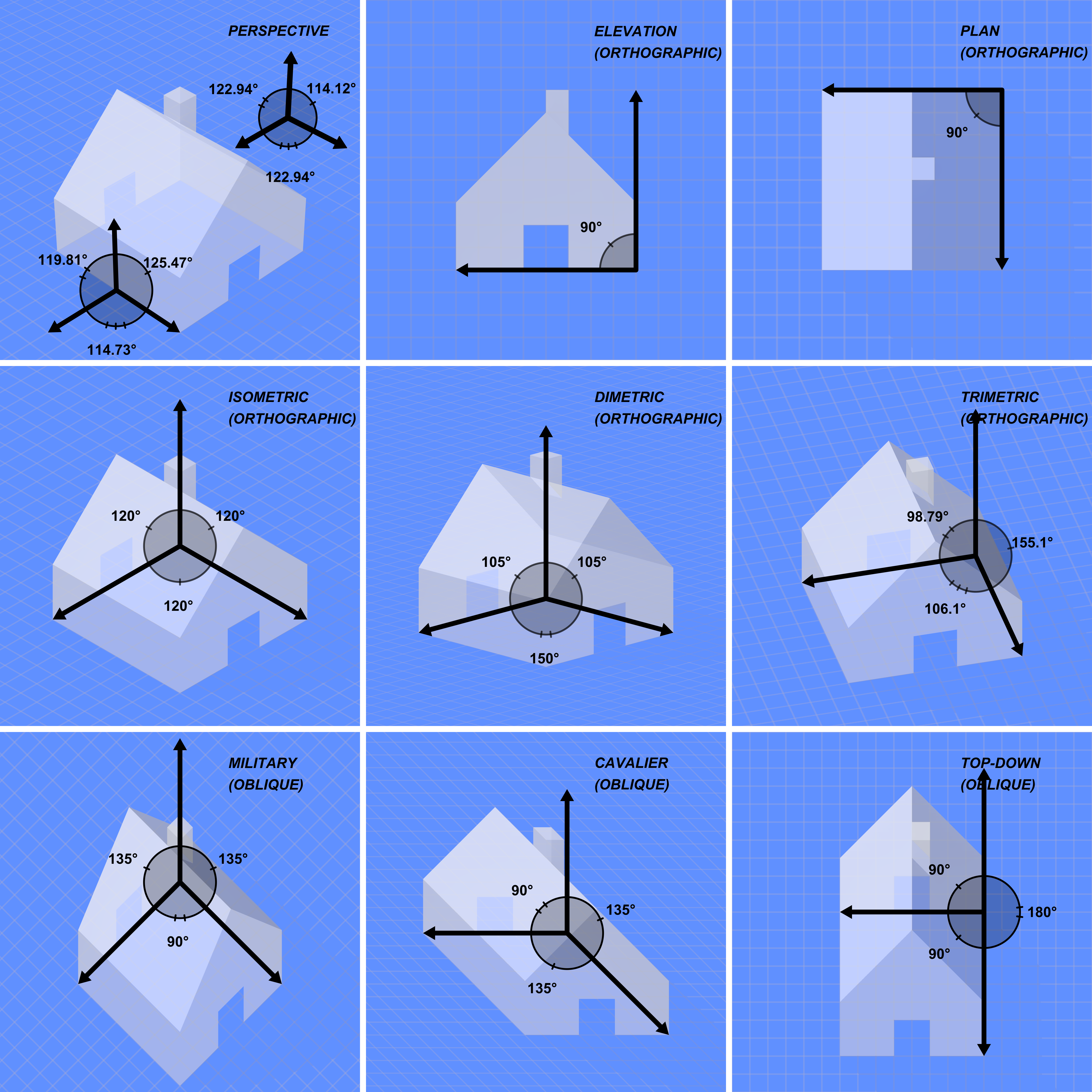
Orthographic projection (also orthogonal projection and analemma) is a means of representing three-dimensional objects in two dimensions. Orthographic projection is a form of parallel projection in which all the projection lines are orthogonal to the projection plane, resulting in every plane of the scene appearing in affine transformation on the viewing surface. The obverse of an orthographic projection is an oblique projection, which is a parallel projection in which the projection lines are ''not'' orthogonal to the projection plane. The term ''orthographic'' sometimes means a technique in multiview projection in which principal axes or the planes of the subject are also parallel with the projection plane to create the ''primary views''. If the principal planes or axes of an object in an orthographic projection are ''not'' parallel with the projection plane, the depiction is called ''axonometric'' or an ''auxiliary views''. (''Axonometric projection'' is synonymous with ''par ... [...More Info...] [...Related Items...] OR: [Wikipedia] [Google] [Baidu] |
Orthographic Projection
Orthographic projection (also orthogonal projection and analemma) is a means of representing three-dimensional objects in two dimensions. Orthographic projection is a form of parallel projection in which all the projection lines are orthogonal to the projection plane, resulting in every plane of the scene appearing in affine transformation on the viewing surface. The obverse of an orthographic projection is an oblique projection, which is a parallel projection in which the projection lines are ''not'' orthogonal to the projection plane. The term ''orthographic'' sometimes means a technique in multiview projection in which principal axes or the planes of the subject are also parallel with the projection plane to create the ''primary views''. If the principal planes or axes of an object in an orthographic projection are ''not'' parallel with the projection plane, the depiction is called ''axonometric'' or an ''auxiliary views''. (''Axonometric projection'' is synonymous with ' ... [...More Info...] [...Related Items...] OR: [Wikipedia] [Google] [Baidu] |
Prefabricated Structure
Prefabrication is the practice of assembling components of a structure in a factory or other manufacturing site, and transporting complete assemblies or sub-assemblies to the construction site where the structure is to be located. The term is used to distinguish this process from the more conventional construction practice of transporting the basic materials to the construction site where all assembly is carried out. The term ''prefabrication'' also applies to the manufacturing of things other than structures at a fixed site. It is frequently used when fabrication of a section of a machine or any movable structure is shifted from the main manufacturing site to another location, and the section is supplied assembled and ready to fit. It is not generally used to refer to electrical or electronic components of a machine, or mechanical parts such as pumps, gearboxes and compressors which are usually supplied as separate items, but to sections of the body of the machine which in the ... [...More Info...] [...Related Items...] OR: [Wikipedia] [Google] [Baidu] |
Construction Drawing
An engineering drawing is a type of technical drawing that is used to convey information about an object. A common use is to specify the geometry necessary for the construction of a component and is called a detail drawing. Usually, a number of drawings are necessary to completely specify even a simple component. The drawings are linked together by a master drawing or assembly drawing which gives the ''drawing numbers'' of the subsequent detailed components, quantities required, construction materials and possibly 3D images that can be used to locate individual items. Although mostly consisting of pictographic representations, abbreviations and symbols are used for brevity and additional textual explanations may also be provided to convey the necessary information. The process of producing engineering drawings is often referred to as technical drawing or drafting (draughting). Drawings typically contain multiple views of a component, although additional ''scratch views'' may ... [...More Info...] [...Related Items...] OR: [Wikipedia] [Google] [Baidu] |
Lettering
Lettering is an umbrella term that covers the art of drawing letters, instead of simply writing them. Lettering is considered an art form, where each letter in a phrase or quote acts as an illustration. Each letter is created with attention to detail and has a unique role within a composition., Lettering is created as an image, with letters that are meant to be used in a unique configuration. Lettering words do not always translate into alphabets that can later be used in a typeface, since they are created with a specific word in mind., Examples Lettering includes that used for purposes of blueprints and comic books, as well as decorative lettering such as sign painting and custom graphics. For instance; on posters, for a letterhead or business wordmark, lettering in stone, lettering for advertisements, tire lettering, fileteado, graffiti, or on chalkboards. Lettering may be drawn, incised, applied using stencils, using a digital medium with a stylus, or a vector prog ... [...More Info...] [...Related Items...] OR: [Wikipedia] [Google] [Baidu] |
Cone (geometry)
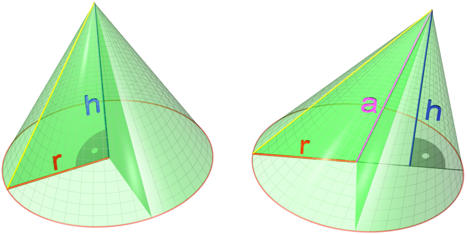
A cone is a three-dimensional geometric shape that tapers smoothly from a flat base (frequently, though not necessarily, circular) to a point called the apex or vertex. A cone is formed by a set of line segments, half-lines, or lines connecting a common point, the apex, to all of the points on a base that is in a plane that does not contain the apex. Depending on the author, the base may be restricted to be a circle, any one-dimensional quadratic form in the plane, any closed one-dimensional figure, or any of the above plus all the enclosed points. If the enclosed points are included in the base, the cone is a solid object; otherwise it is a two-dimensional object in three-dimensional space. In the case of a solid object, the boundary formed by these lines or partial lines is called the ''lateral surface''; if the lateral surface is unbounded, it is a conical surface. In the case of line segments, the cone does not extend beyond the base, while in the case of hal ... [...More Info...] [...Related Items...] OR: [Wikipedia] [Google] [Baidu] |
Gear
A gear is a rotating circular machine part having cut teeth or, in the case of a cogwheel or gearwheel, inserted teeth (called ''cogs''), which mesh with another (compatible) toothed part to transmit (convert) torque and speed. The basic principle behind the operation of gears is analogous to the basic principle of levers. A gear may also be known informally as a cog. Geared devices can change the speed, torque, and direction of a power source. Gears of different sizes produce a change in torque, creating a mechanical advantage, through their ''gear ratio'', and thus may be considered a simple machine. The rotational speeds, and the torques, of two meshing gears differ in proportion to their diameters. The teeth on the two meshing gears all have the same shape. Two or more meshing gears, working in a sequence, are called a gear train or a ''transmission''. The gears in a transmission are analogous to the wheels in a crossed, belt pulley system. An advantage of gears is t ... [...More Info...] [...Related Items...] OR: [Wikipedia] [Google] [Baidu] |
Profile (engineering)
In standardization, a profile is a subset internal to a specification. Aspects of a complex technical specification may necessarily have more than one interpretation, and there are probably many optional features. These aspects constitute a profile of the standard. Two implementations engineered from the same description may not interoperate due to having a different profile of the standard. Vendors can even ignore features that they view as unimportant, yet prevail in the long run. The use of profiles in these ways can force one interpretation, or create de facto standards from official standards. Engineers can design or procure by using a profile to ensure interoperability. For example, the International Standard Profile, ISP, is used by the ISO in their ISO ISP series of standards; in the context of OSI networking, Britain uses the UK-GOSIP profile and the US uses US- GOSIP; there are also various mobile profiles adopted by the W3C for web standards. In particular, imple ... [...More Info...] [...Related Items...] OR: [Wikipedia] [Google] [Baidu] |
Paper Size
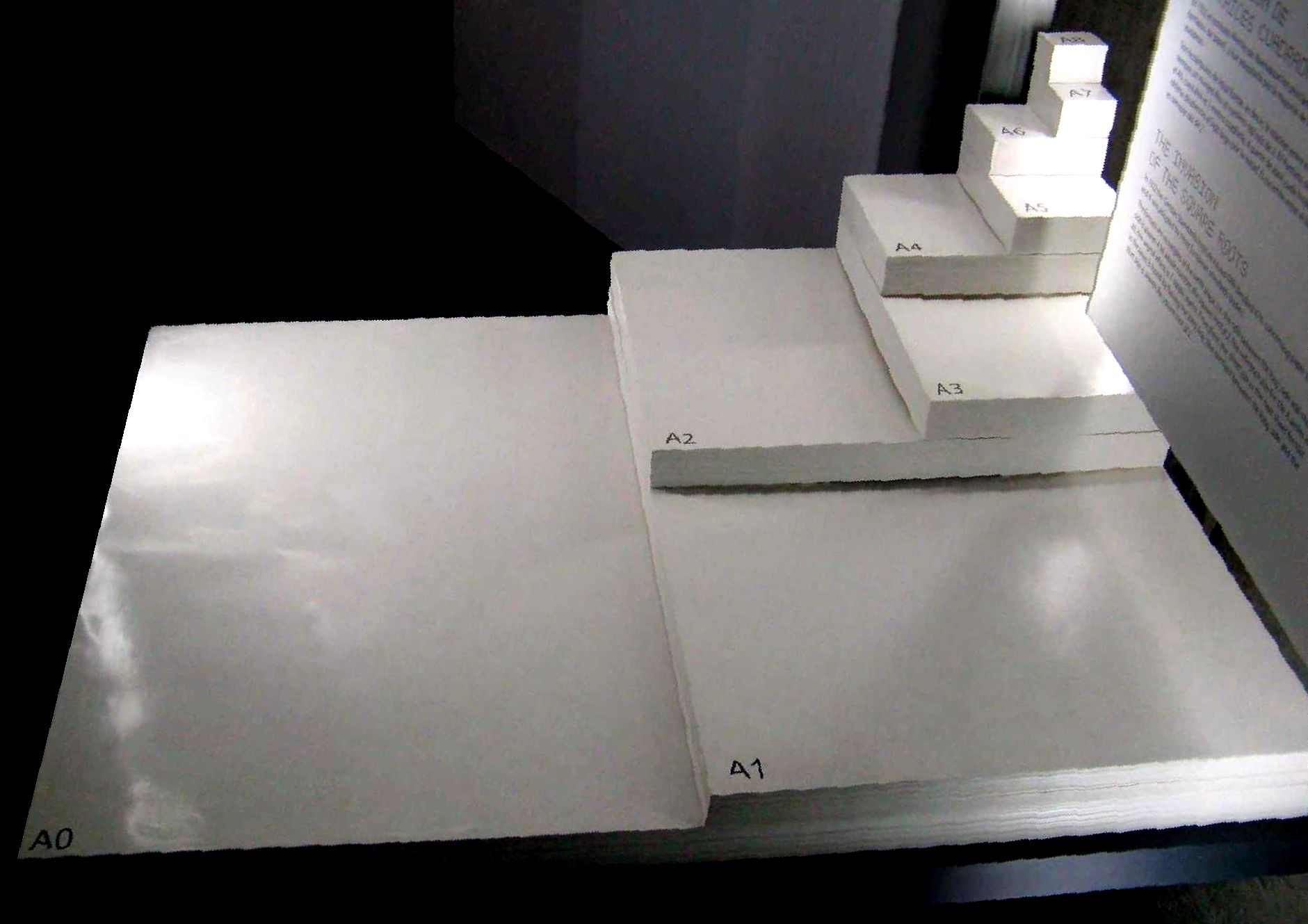
Paper size standards govern the size of sheets of paper used as writing paper, stationery, cards, and for some printed documents. The ISO 216 standard, which includes the commonly used A4 size, is the international standard for paper size. It is used across the world except in North America and parts of Central and South America, where North American paper sizes such as " Letter" and " Legal" are used. The international standard for envelopes is the C series of ISO 269. International paper sizes The international paper size standard is ISO 216. It is based on the German DIN 476 standard for paper sizes. ISO paper sizes are all based on a single aspect ratio of the square root of 2, or approximately 1:1.41421. There are different series, as well as several extensions. The following international paper sizes are included in Cascading Style Sheets (CSS): ''A3'', ''A4'', ''A5'', ''B4'', ''B5''. A series There are 11 sizes in the A series, designated A0–A10, ... [...More Info...] [...Related Items...] OR: [Wikipedia] [Google] [Baidu] |
A4 Paper
ISO 216 is an international standard for paper sizes, used around the world except in North America and parts of Latin America. The standard defines the "A", "B" and "C" series of paper sizes, including A4, the most commonly available paper size worldwide. Two supplementary standards, ISO 217 and ISO 269, define related paper sizes; the ISO 269 "C" series is commonly listed alongside the A and B sizes. All ISO 216, ISO 217 and ISO 269 paper sizes (except some envelopes) have the same aspect ratio, , within rounding to millimetres. This ratio has the unique property that when cut or folded in half widthways, the halves also have the same aspect ratio. Each ISO paper size is one half of the area of the next larger size in the same series. Dimensions of A, B and C series History The oldest known mention of the advantages of basing a paper size on an aspect ratio of is found in a letter written on 25 October 1786 by the German scientist Georg Christoph Lichtenbe ... [...More Info...] [...Related Items...] OR: [Wikipedia] [Google] [Baidu] |


.jpg)


