|
Feature (CAD)
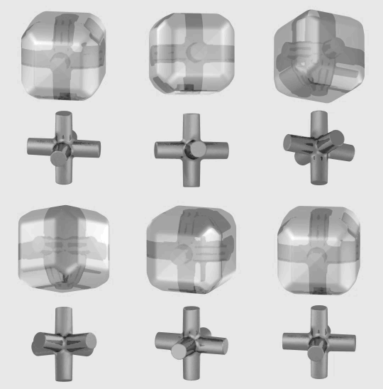
The term "feature" implies different meanings in different engineering disciplines. This has resulted in many ambiguous definitions for feature. A feature, in computer-aided design (CAD), usually refers to a region of a part with some interesting geometric or topological properties.Pratt M.J. and Wilson P.R., 1985, Requirements for support of form features in a solid modeling system, ''CAM-I'', R-85-ASPP-01 These are more precisely called form features. Form features contain both shape information and parametric information of a region of interest. They are now ubiquitous in most current CAD software, where they are used as the primary means of creating 3D geometric models. Examples of form features are extruded boss, loft, etc. Form feature is not the only type of feature that is discussed in CAD literature. Sometimes a part's functional or manufacturing features of the subject of attention.Regli W.C., 1995, Geometric algorithms for recognition of features from solid models, PhD ... [...More Info...] [...Related Items...] OR: [Wikipedia] [Google] [Baidu] |
Computer-aided Design
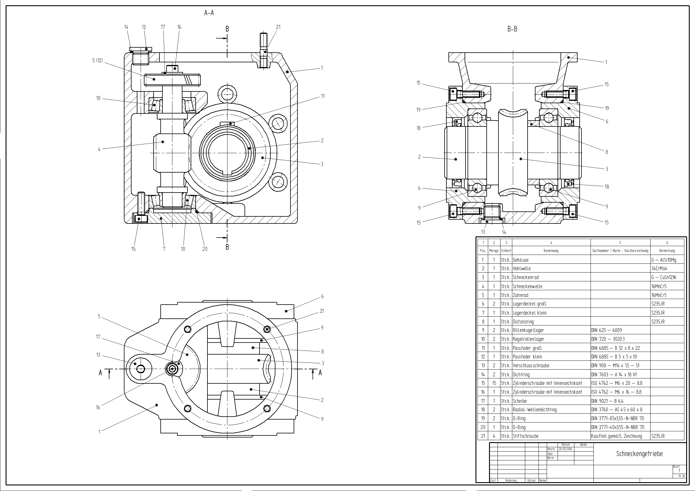
Computer-aided design (CAD) is the use of computers (or ) to aid in the creation, modification, analysis, or optimization of a design. This software is used to increase the productivity of the designer, improve the quality of design, improve communications through documentation, and to create a database for manufacturing. Designs made through CAD software are helpful in protecting products and inventions when used in patent applications. CAD output is often in the form of electronic files for print, machining, or other manufacturing operations. The terms computer-aided drafting (CAD) and computer aided design and drafting (CADD) are also used. Its use in designing electronic systems is known as '' electronic design automation'' (''EDA''). In mechanical design it is known as ''mechanical design automation'' (''MDA''), which includes the process of creating a technical drawing with the use of computer software. CAD software for mechanical design uses either vector-based graphics ... [...More Info...] [...Related Items...] OR: [Wikipedia] [Google] [Baidu] |
Computer-aided Manufacturing
Computer-aided manufacturing (CAM) also known as computer-aided modeling or computer-aided machining is the use of software to control machine tools in the manufacturing of work pieces. This is not the only definition for CAM, but it is the most common; CAM may also refer to the use of a computer to assist in all operations of a manufacturing plant, including planning, management, transportation and storage. Its primary purpose is to create a faster production process and components and tooling with more precise dimensions and material consistency, which in some cases, uses only the required amount of raw material (thus minimizing waste), while simultaneously reducing energy consumption. CAM is now a system used in schools and lower educational purposes. CAM is a subsequent computer-aided process after computer-aided design (CAD) and sometimes computer-aided engineering (CAE), as the model generated in CAD and verified in CAE can be input into CAM software, which then controls the ... [...More Info...] [...Related Items...] OR: [Wikipedia] [Google] [Baidu] |
Lycourgos Kyprianou
Lycourgos Kyprianou (born 1954/1955) is a Cypriot businessman, and the former chairman of GlobalSoft and AremisSoft Corp. Together with his business partner, Roys Poyiadjis Roys Poyiadjis (born 14 August 1965) is a Greek Cypriot entrepreneur and financier. He is most notable for his role in the largest Securities and Exchange Commission (SEC) settlement with an individual, $200 million, after he pleaded guilty t ..., he has been charged with defrauding investors of $565 million. He fled to Cyprus, where he remains, and in 2018, the Cyprus justice ministry confirmed that no Cypriot has been extradited to the US. Fraud charges In 2002, Kyprianou was charged with securities fraud and money laundering by the US authorities. The fraud was uncovered in 2001, after which Kyprianou and Poyiadjis fled to Cyprus. In July 2005, a Nicosia court ordered a global freeze on Kyprianou's assets following an alleged US$565 million perpetrated by Kyprianou and Poyiadjis on the shareholders of ... [...More Info...] [...Related Items...] OR: [Wikipedia] [Google] [Baidu] |
Computer Integrated Manufacturing
Computer-integrated manufacturing (CIM) is the manufacturing approach of using computers to control the entire production process. This integration allows individual processes to exchange information with each part. Manufacturing can be faster and less error-prone by the integration of computers. Typically CIM relies on closed-loop control processes based on real-time input from sensors. It is also known as ''flexible design and manufacturing''. Overview # Computer-integrated manufacturing is used in automotive, aviation, space, and ship building industries. # The term "computer-integrated manufacturing" is both a method of manufacturing and the name of a computer-automated system in which individual engineering, production, marketing, and support functions of a manufacturing enterprise are organized. # In a CIM system functional areas such as design, analysis, planning, purchasing, cost accounting, inventory control, and distribution are linked through the computer with facto ... [...More Info...] [...Related Items...] OR: [Wikipedia] [Google] [Baidu] |
Parametric Feature Based Modeler
Solid modeling (or solid modelling) is a consistent set of principles for mathematical and computer modeling of three-dimensional shapes '' (solids)''. Solid modeling is distinguished from related areas of geometric modeling and computer graphics, such as '' 3D modeling'', by its emphasis on physical fidelity. Together, the principles of geometric and solid modeling form the foundation of 3D- computer-aided design and in general support the creation, exchange, visualization, animation, interrogation, and annotation of digital models of physical objects. Overview The use of solid modeling techniques allows for the automation process of several difficult engineering calculations that are carried out as a part of the design process. Simulation, planning, and verification of processes such as machining and assembly were one of the main catalysts for the development of solid modeling. More recently, the range of supported manufacturing applications has been greatly expanded to ... [...More Info...] [...Related Items...] OR: [Wikipedia] [Google] [Baidu] |
Space Mapping
The space mapping methodology for modeling and design optimization of engineering systems was first discovered by John Bandler in 1993. It uses relevant existing knowledge to speed up model generation and design optimization of a system. The knowledge is updated with new validation information from the system when available. Concept The space mapping methodology employs a "quasi-global" formulation that intelligently links companion "coarse" (ideal or low-fidelity) and "fine" (practical or high-fidelity) models of different complexities. In engineering design, space mapping aligns a very fast coarse model with the expensive-to-compute fine model so as to avoid direct expensive optimization of the fine model. The alignment can be done either off-line (model enhancement) or on-the-fly with surrogate updates (e.g., aggressive space mapping). Methodology At the core of the process is a pair of models: one very accurate but too expensive to use directly with a conventional optimizati ... [...More Info...] [...Related Items...] OR: [Wikipedia] [Google] [Baidu] |
STEP-NC
STEP-NC is a machine tool control language that extends the ISO 10303 STEP standards with the machining model in ISO 14649, adding geometric dimension and tolerance data for inspection, and the STEP PDM model for integration into the wider enterprise. The combined result has been standardized as ISO 10303-238 (also known as AP238). STEP-NC was designed to replace ISO 6983/RS274D G-codes with a modern, associative communications protocol that connects computer numerical controlled (CNC) process data to a product description of the part being machined. A STEP-NC program can use the full range of geometric constructs from the STEP standard to communicate device-independent toolpaths to the CNC. It can provide CAM operational descriptions and STEP CAD geometry to the CNC so workpieces, stock, fixtures and cutting tool shapes can be visualized and analyzed in the context of the toolpaths. STEP GD&T information can also be added to enable quality measurement on the control, and ... [...More Info...] [...Related Items...] OR: [Wikipedia] [Google] [Baidu] |


