|
Fresnel Number
The Fresnel number (''F''), named after the physicist Augustin-Jean Fresnel, is a dimensionless number occurring in optics, in particular in diffraction, scalar diffraction theory. Definition For an electromagnetic wave passing through an aperture and hitting a screen, the Fresnel number ''F'' is defined as : F = \frac where : a is the characteristic size (e.g. radius) of the aperture : L is the distance of the screen from the aperture : \lambda is the incident wavelength. Conceptually, it is the number of half-Periodic function, period zones in the wavefront amplitude, counted from the center to the edge of the aperture, as seen from the observation point (the center of the imaging screen), where a half-period zone is defined so that the wavefront Phase (waves), phase changes by \pi when moving from one half-period zone to the next. An equivalent definition is that the Fresnel number is the difference, expressed in half-wavelengths, between the ''slant'' distance from the obs ... [...More Info...] [...Related Items...] OR: [Wikipedia] [Google] [Baidu] |
Augustin-Jean Fresnel
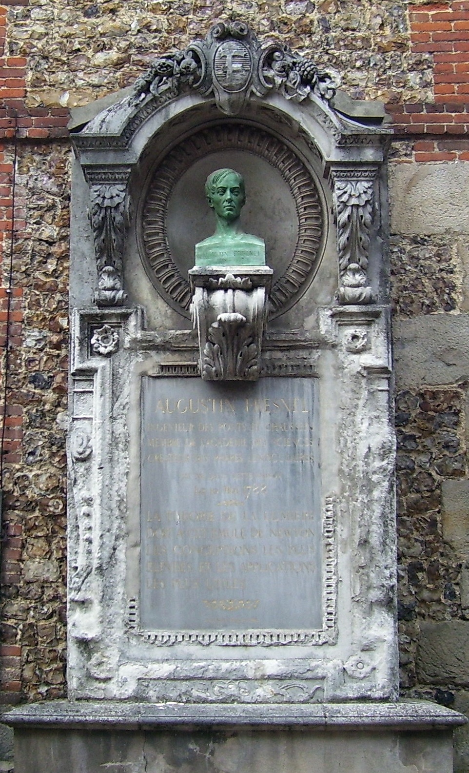
Augustin-Jean Fresnel (10 May 1788 – 14 July 1827) was a French civil engineer and physicist whose research in optics led to the almost unanimous acceptance of the wave theory of light, excluding any remnant of Isaac Newton, Newton's corpuscular theory of light, corpuscular theory, from the late 1830s until the end of the 19th century. He is perhaps better known for inventing the Catadioptric system, catadioptric (reflective/refractive) Fresnel lens and for pioneering the use of "stepped" lenses to extend the visibility of lighthouses, saving countless lives at sea. The simpler Dioptrics, dioptric (purely refractive) stepped lens, first proposed by Georges-Louis Leclerc, Comte de Buffon, Count Buffon and independently reinvented by Fresnel, is used in screen magnifying glass, magnifiers and in condenser lenses for overhead projectors. By expressing Christiaan Huygens, Huygens's principle of secondary waves and Thomas Young (scientist), Young's principle of interference ( ... [...More Info...] [...Related Items...] OR: [Wikipedia] [Google] [Baidu] |
Fraunhofer Diffraction
In optics, the Fraunhofer diffraction equation is used to model the diffraction of waves when plane waves are incident on a diffracting object, and the diffraction pattern is viewed at a sufficiently long distance (a distance satisfying Fraunhofer condition) from the object (in the far-field region), and also when it is viewed at the focal plane of an imaging lens. In contrast, the diffraction pattern created near the diffracting object (in the near field region) is given by the Fresnel diffraction equation. The equation was named in honor of Joseph von Fraunhofer although he was not actually involved in the development of the theory. This article explains where the Fraunhofer equation can be applied, and shows Fraunhofer diffraction patterns for various apertures. A detailed mathematical treatment of Fraunhofer diffraction is given in Fraunhofer diffraction equation. Equation When a beam of light is partly blocked by an obstacle, some of the light is scattered around the o ... [...More Info...] [...Related Items...] OR: [Wikipedia] [Google] [Baidu] |
Talbot Effect
The Talbot effect is a diffraction effect first observed in 1836 by Henry Fox Talbot. When a plane wave is incident upon a periodic diffraction grating, the image of the grating is repeated at regular distances away from the grating plane. The regular distance is called the Talbot length, and the repeated images are called self images or Talbot images. Furthermore, at half the Talbot length, a self-image also occurs, but phase-shifted by half a period (the physical meaning of this is that it is laterally shifted by half the width of the grating period). At smaller regular fractions of the Talbot length, sub-images can also be observed. At one quarter of the Talbot length, the self-image is halved in size, and appears with half the period of the grating (thus twice as many images are seen). At one eighth of the Talbot length, the period and size of the images is halved again, and so forth creating a fractal pattern of sub images with ever-decreasing size, often referred to as a Talbo ... [...More Info...] [...Related Items...] OR: [Wikipedia] [Google] [Baidu] |
Near And Far Field
The near field and far field are regions of the electromagnetic (EM) field around an object, such as a transmitting antenna, or the result of radiation scattering off an object. Non-radiative ''near-field'' behaviors dominate close to the antenna or scattering object, while electromagnetic radiation ''far-field'' behaviors dominate at greater distances. Far-field E (electric) and B (magnetic) field strength decreases as the distance from the source increases, resulting in an inverse-square law for the radiated ''power'' intensity of electromagnetic radiation. By contrast, near-field E and B strength decrease more rapidly with distance: the radiative field decreases by the inverse-distance squared, the reactive field by an inverse-cube law, resulting in a diminished power in the parts of the electric field by an inverse fourth-power and sixth-power, respectively. The rapid drop in power contained in the near-field ensures that effects due to the near-field essentially vanish a ... [...More Info...] [...Related Items...] OR: [Wikipedia] [Google] [Baidu] |
Fresnel Zone
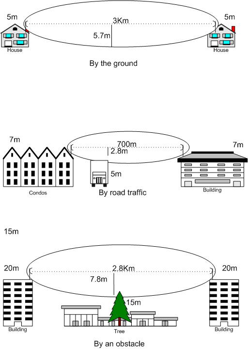
A Fresnel zone ( ), named after physicist Augustin-Jean Fresnel, is one of a series of confocal prolate ellipsoidal regions of space between and around a transmitter and a receiver. The primary wave will travel in a relative straight line from the transmitter to the receiver. Aberrant transmitted radio, sound, or light waves which are transmitted at the same time can follow slightly different paths before reaching a receiver, especially if there are obstructions or deflecting objects between the two. The two waves can arrive at the receiver at slightly different times and the aberrant wave may arrive out of phase with the primary wave due to the different path lengths. Depending on the magnitude of the phase difference between the two waves, the waves can interfere constructively or destructively. The size of the calculated Fresnel zone at any particular distance from the transmitter and receiver can help to predict whether obstructions or discontinuities along the path wi ... [...More Info...] [...Related Items...] OR: [Wikipedia] [Google] [Baidu] |
Fresnel Integral
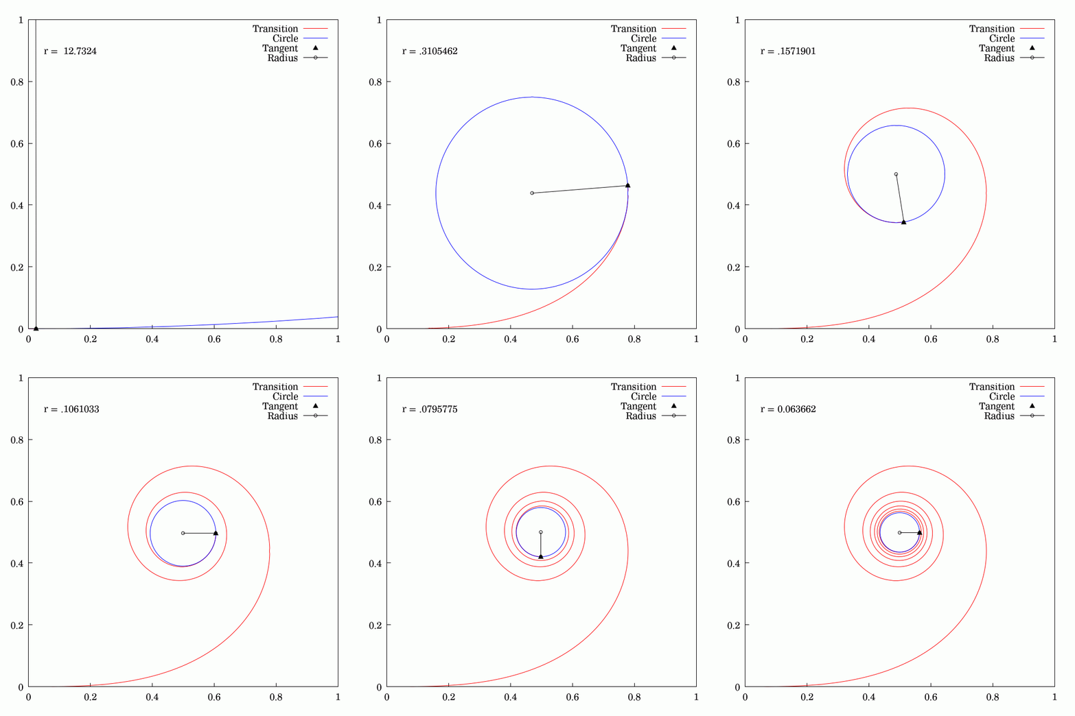
250px, Plots of and . The maximum of is about . If the integrands of and were defined using instead of , then the image would be scaled vertically and horizontally (see below). The Fresnel integrals and are two transcendental functions named after Augustin-Jean Fresnel that are used in optics and are closely related to the error function (). They arise in the description of near-field Fresnel diffraction phenomena and are defined through the following integral representations: S(x) = \int_0^x \sin\left(t^2\right)\,dt, \quad C(x) = \int_0^x \cos\left(t^2\right)\,dt. The simultaneous parametric plot of and is the Euler spiral (also known as the Cornu spiral or clothoid). Definition 250px, Fresnel integrals with arguments instead of converge to instead of . The Fresnel integrals admit the following power series expansions that converge for all : \begin S(x) &= \int_0^x \sin\left(t^2\right)\,dt = \sum_^(-1)^n \frac, \\ C(x) &= \int_0^x \cos\left(t^2\right)\,dt = ... [...More Info...] [...Related Items...] OR: [Wikipedia] [Google] [Baidu] |
Fresnel Imager
A Fresnel imager is a proposed ultra-lightweight design for a space telescope that uses a Fresnel lens, Fresnel array as primary optics instead of a typical lens. It focuses light with a thin opaque foil sheet punched with specially shaped holes, thus focusing light on a certain point by using the phenomenon of diffraction. Such patterned sheets, called Fresnel zone plates, have long been used for focusing laser beams, but have so far not been used for astronomy. No optical material is involved in the focusing process as in traditional telescopes. Rather, the light collected by the Fresnel array is concentrated on smaller classical optics (e.g. 1/20 of the array size), to form a final image. The long focal lengths of the Fresnel imager (a few kilometers) require operation by two-vessel formation flying in space at the Lagrangian point#L2, L2 Sun-Earth Lagrangian point. In this two-spacecraft formation-flying instrument, one spacecraft holds the focussing element: the Fresnel interfe ... [...More Info...] [...Related Items...] OR: [Wikipedia] [Google] [Baidu] |
Fraunhofer Distance
The Fraunhofer distance, named after Joseph von Fraunhofer, is the value of: :d = , where D is the largest dimension of the radiator (in the case of a magnetic loop antenna, the diameter) and is the wavelength of the radio wave. This distance provides the limit between the near and far field. See also * Fresnel number * Fresnel diffraction and Fraunhofer diffraction * Antenna measurement Antenna measurement techniques refers to the testing of antennas to ensure that the antenna meets specifications or simply to characterize it. Typical parameters of antennas are gain, bandwidth, radiation pattern, beamwidth, polarization, and ... Diffraction Antennas Antennas (radio) {{optics-stub ... [...More Info...] [...Related Items...] OR: [Wikipedia] [Google] [Baidu] |
Rayleigh Length
In optics and especially laser science, the Rayleigh length or Rayleigh range, z_\mathrm, is the distance along the propagation direction of a beam from the waist to the place where the area of the cross section is doubled. A related parameter is the confocal parameter, ''b'', which is twice the Rayleigh length. The Rayleigh length is particularly important when beams are modeled as Gaussian beams. Explanation For a Gaussian beam propagating in free space along the \hat axis with wave number k = 2\pi/\lambda, the Rayleigh length is given by :z_\mathrm = \frac = \frac k w_0^2 where \lambda is the wavelength (the vacuum wavelength divided by n, the index of refraction) and w_0 is the beam waist, the radial size of the beam at its narrowest point. This equation and those that follow assume that the waist is not extraordinarily small; w_0 \ge 2\lambda/\pi. The radius of the beam at a distance z from the waist is :w(z) = w_0 \, \sqrt . The minimum value of w(z) occurs at w(0) ... [...More Info...] [...Related Items...] OR: [Wikipedia] [Google] [Baidu] |
Gaussian Beam
In optics, a Gaussian beam is a beam of electromagnetic radiation with high monochromaticity whose amplitude envelope in the transverse plane is given by a Gaussian function; this also implies a Gaussian intensity (irradiance) profile. This fundamental (or TEM00) transverse Gaussian mode describes the intended output of most (but not all) lasers, as such a beam can be focused into the most concentrated spot. When such a beam is refocused by a lens, the transverse ''phase'' dependence is altered; this results in a ''different'' Gaussian beam. The electric and magnetic field amplitude profiles along any such circular Gaussian beam (for a given wavelength and polarization) are determined by a single parameter: the so-called waist . At any position relative to the waist (focus) along a beam having a specified , the field amplitudes and phases are thereby determinedSvelto, pp. 153–5. as detailed below. The equations below assume a beam with a circular cross-section at all va ... [...More Info...] [...Related Items...] OR: [Wikipedia] [Google] [Baidu] |
Aliasing
In signal processing and related disciplines, aliasing is an effect that causes different signals to become indistinguishable (or ''aliases'' of one another) when sampled. It also often refers to the distortion or artifact that results when a signal reconstructed from samples is different from the original continuous signal. Aliasing can occur in signals sampled in time, for instance digital audio, or the stroboscopic effect, and is referred to as temporal aliasing. It can also occur in spatially sampled signals (e.g. moiré patterns in digital images); this type of aliasing is called spatial aliasing. Aliasing is generally avoided by applying low-pass filters or anti-aliasing filters (AAF) to the input signal before sampling and when converting a signal from a higher to a lower sampling rate. Suitable reconstruction filtering should then be used when restoring the sampled signal to the continuous domain or converting a signal from a lower to a higher sampling rate. For spa ... [...More Info...] [...Related Items...] OR: [Wikipedia] [Google] [Baidu] |
Focus (optics)
In geometrical optics, a focus, also called an image point, is a point where light rays originating from a point on the object converge. Although the focus is conceptually a point, physically the focus has a spatial extent, called the blur circle. This non-ideal focusing may be caused by aberrations of the imaging optics. In the absence of significant aberrations, the smallest possible blur circle is the Airy disc, which is caused by diffraction from the optical system's aperture. Aberrations tend to worsen as the aperture diameter increases, while the Airy circle is smallest for large apertures. An image, or image point or region, is in focus if light from object points is converged almost as much as possible in the image, and out of focus if light is not well converged. The border between these is sometimes defined using a "circle of confusion" criterion. A principal focus or focal point is a special focus: * For a lens, or a spherical or parabolic mirror, it is a point ... [...More Info...] [...Related Items...] OR: [Wikipedia] [Google] [Baidu] |


