|
Field Pattern
In the field of antenna design the term radiation pattern (or antenna pattern or far-field pattern) refers to the ''directional'' (angular) dependence of the strength of the radio waves from the antenna or other source.Constantine A. Balanis: “Antenna Theory, Analysis and Design”, John Wiley & Sons, Inc., 2nd ed. 1982 David K Cheng: “Field and Wave Electromagnetics”, Addison-Wesley Publishing Company Inc., Edition 2, 1998. Edward C. Jordan & Keith G. Balmain; “Electromagnetic Waves and Radiating Systems” (2nd ed. 1968) Prentice-Hall. Particularly in the fields of fiber optics, lasers, and integrated optics, the term radiation pattern may also be used as a synonym for the near-field pattern or Fresnel pattern.Institute of Electrical and Electronics Engineers, “The IEEE standard dictionary of electrical and electronics terms”; 6th ed. New York, N.Y., Institute of Electrical and Electronics Engineers, c1997. IEEE Std 100-1996. d. Standards Coordinating Committee 10 ... [...More Info...] [...Related Items...] OR: [Wikipedia] [Google] [Baidu] |
Horizontal Plane
In astronomy, geography, and related sciences and contexts, a '' direction'' or ''plane'' passing by a given point is said to be vertical if it contains the local gravity direction at that point. Conversely, a direction or plane is said to be horizontal if it is perpendicular to the vertical direction. In general, something that is vertical can be drawn from up to down (or down to up), such as the y-axis in the Cartesian coordinate system. Historical definition The word ''horizontal'' is derived from the Latin , which derives from the Greek , meaning 'separating' or 'marking a boundary'. The word ''vertical'' is derived from the late Latin ', which is from the same root as ''vertex'', meaning 'highest point' or more literally the 'turning point' such as in a whirlpool. Girard Desargues defined the vertical to be perpendicular to the horizon in his 1636 book ''Perspective''. Geophysical definition The plumb line and spirit level In physics, engineering and construction, th ... [...More Info...] [...Related Items...] OR: [Wikipedia] [Google] [Baidu] |
Interference (wave Propagation)
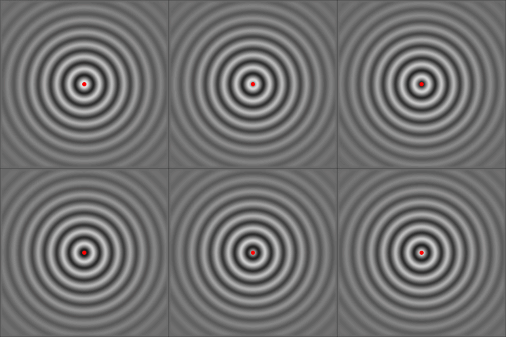
In physics, interference is a phenomenon in which two waves combine by adding their displacement together at every single point in space and time, to form a resultant wave of greater, lower, or the same amplitude. Constructive and destructive interference result from the interaction of waves that are correlated or coherent with each other, either because they come from the same source or because they have the same or nearly the same frequency. Interference effects can be observed with all types of waves, for example, light, radio, acoustic, surface water waves, gravity waves, or matter waves. Etymology The word ''interference'' is derived from the Latin words ''inter'' which means "between" and ''fere'' which means "hit or strike", and was coined by Thomas Young in 1801. Mechanisms The principle of superposition of waves states that when two or more propagating waves of the same type are incident on the same point, the resultant amplitude at that point is equal to th ... [...More Info...] [...Related Items...] OR: [Wikipedia] [Google] [Baidu] |
Omnidirectional Antenna
In radio communication, an omnidirectional antenna is a class of antenna which radiates equal radio power in all directions perpendicular to an axis (azimuthal directions), with power varying with angle to the axis (elevation angle), declining to zero on the axis. When graphed in three dimensions ''(see graph)'' this radiation pattern is often described as ''doughnut-shaped''. Note that this is different from an isotropic antenna, which radiates equal power in ''all'' directions, having a ''spherical'' radiation pattern. Omnidirectional antennas oriented vertically are widely used for nondirectional antennas on the surface of the Earth because they radiate equally in all horizontal directions, while the power radiated drops off with elevation angle so little radio energy is aimed into the sky or down toward the earth and wasted. Omnidirectional antennas are widely used for radio broadcasting antennas, and in mobile devices that use radio such as cell phones, FM radios, walkie ... [...More Info...] [...Related Items...] OR: [Wikipedia] [Google] [Baidu] |
Axial Symmetry
Axial symmetry is symmetry around an axis; an object is axially symmetric if its appearance is unchanged if rotated around an axis. glossary of meteorology. Retrieved 2010-04-08. For example, a without trademark or other design, or a plain white tea saucer, looks the same if it is rotated by any angle about the line passing lengthwise through its center, so it is axially symmetric. Axial symmetry can also be |
Dipole Antenna
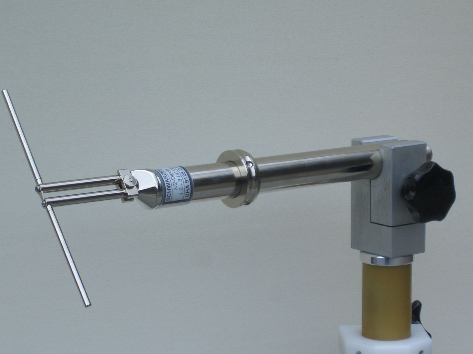
In radio and telecommunications a dipole antenna or doublet is the simplest and most widely used class of antenna. The dipole is any one of a class of antennas producing a radiation pattern approximating that of an elementary electric dipole with a radiating structure supporting a line current so energized that the current has only one node at each end. A dipole antenna commonly consists of two identical conductive elements such as metal wires or rods. The driving current from the transmitter is applied, or for receiving antennas the output signal to the receiver is taken, between the two halves of the antenna. Each side of the feedline to the transmitter or receiver is connected to one of the conductors. This contrasts with a monopole antenna, which consists of a single rod or conductor with one side of the feedline connected to it, and the other side connected to some type of ground. A common example of a dipole is the "rabbit ears" television antenna found on broadcast telev ... [...More Info...] [...Related Items...] OR: [Wikipedia] [Google] [Baidu] |
Monopole Antenna
A monopole antenna is a class of radio antenna consisting of a straight rod-shaped conductor, often mounted perpendicularly over some type of conductive surface, called a ground plane. The driving signal from the transmitter is applied, or for receiving antennas the output signal to the receiver is taken, between the lower end of the monopole and the ground plane. One side of the antenna feedline is attached to the lower end of the monopole, and the other side is attached to the ground plane, which is often the Earth. This contrasts with a dipole antenna which consists of two identical rod conductors, with the signal from the transmitter applied between the two halves of the antenna. The monopole is often used as a resonant antenna; the rod functions as an open resonator for radio waves, oscillating with standing waves of voltage and current along its length. Therefore the length of the antenna is determined by the wavelength of the radio waves it is used with. The most co ... [...More Info...] [...Related Items...] OR: [Wikipedia] [Google] [Baidu] |
Antenna Gain
In electromagnetics, an antenna's gain is a key performance parameter which combines the antenna's directivity and radiation efficiency. The term ''power gain'' has been deprecated by IEEE. In a transmitting antenna, the gain describes how well the antenna converts input power into radio waves headed in a specified direction. In a receiving antenna, the gain describes how well the antenna converts radio waves arriving from a specified direction into electrical power. When no direction is specified, gain is understood to refer to the peak value of the gain, the gain in the direction of the antenna's main lobe. A plot of the gain as a function of direction is called the antenna pattern or radiation pattern. It is not to be confused with directivity, which does ''not'' take an antenna's radiation efficiency into account. Gain or 'absolute gain' is defined as "The ratio of the radiation intensity in a given direction to the radiation intensity that would be produced if the p ... [...More Info...] [...Related Items...] OR: [Wikipedia] [Google] [Baidu] |
Isotropic Antenna
An isotropic radiator is a theoretical point source of electromagnetic or sound waves which radiates the same intensity of radiation in all directions. It has no preferred direction of radiation. It radiates uniformly in all directions over a sphere centred on the source. Isotropic radiators are used as reference radiators with which other sources are compared, for example in determining the gain of antennas. A coherent isotropic radiator of electromagnetic waves is theoretically impossible, but incoherent radiators can be built. An isotropic sound radiator is possible because sound is a longitudinal wave. The unrelated term ''isotropic radiation'' refers to radiation which has the same intensity in all directions, thus an isotropic radiator does ''not'' radiate isotropic radiation. Physics In physics, an isotropic radiator is a point radiation or sound source. At a distance, the sun is an isotropic radiator of electromagnetic radiation. Antenna theory In antenna the ... [...More Info...] [...Related Items...] OR: [Wikipedia] [Google] [Baidu] |
Dipole Radiation
In physics, a dipole () is an electromagnetic phenomenon which occurs in two ways: *An electric dipole deals with the separation of the positive and negative electric charges found in any electromagnetic system. A simple example of this system is a pair of charges of equal magnitude but opposite sign separated by some typically small distance. (A permanent electric dipole is called an electret.) *A magnetic dipole is the closed circulation of an electric current system. A simple example is a single loop of wire with constant current through it. A bar magnet is an example of a magnet with a permanent magnetic dipole moment. Dipoles, whether electric or magnetic, can be characterized by their dipole moment, a vector quantity. For the simple electric dipole, the electric dipole moment points from the negative charge towards the positive charge, and has a magnitude equal to the strength of each charge times the separation between the charges. (To be precise: for the definition of th ... [...More Info...] [...Related Items...] OR: [Wikipedia] [Google] [Baidu] |
Electromagnetic Radiation
In physics, electromagnetic radiation (EMR) consists of waves of the electromagnetic field, electromagnetic (EM) field, which propagate through space and carry momentum and electromagnetic radiant energy. It includes radio waves, microwaves, infrared, Light, (visible) light, ultraviolet, X-rays, and gamma rays. All of these waves form part of the electromagnetic spectrum. Classical electromagnetism, Classically, electromagnetic radiation consists of electromagnetic waves, which are synchronized oscillations of electric field, electric and magnetic fields. Depending on the frequency of oscillation, different wavelengths of electromagnetic spectrum are produced. In a vacuum, electromagnetic waves travel at the speed of light, commonly denoted ''c''. In homogeneous, isotropic media, the oscillations of the two fields are perpendicular to each other and perpendicular to the direction of energy and wave propagation, forming a transverse wave. The position of an electromagnetic wave w ... [...More Info...] [...Related Items...] OR: [Wikipedia] [Google] [Baidu] |
Sidelobes En
In antenna engineering, sidelobes are the lobes (local maxima) of the far field radiation pattern of an antenna or other radiation source, that are not the ''main lobe''. The radiation pattern of most antennas shows a pattern of "''lobes''" at various angles, directions where the radiated signal strength reaches a maximum, separated by "''nulls''", angles at which the radiated signal strength falls to zero. This can be viewed as the diffraction pattern of the antenna. In a directional antenna in which the objective is to emit the radio waves in one direction, the lobe in that direction is designed to have a larger field strength than the others; this is the "''main lobe''". The other lobes are called "''sidelobes''", and usually represent unwanted radiation in undesired directions. The sidelobe directly behind the main lobe is called the back lobe. The longer the antenna relative to the radio wavelength, the more lobes its radiation pattern has. In transmitting antennas, ... [...More Info...] [...Related Items...] OR: [Wikipedia] [Google] [Baidu] |


