|
Digital Clock Manager
A digital clock manager (DCM) is an electronic component available on some field-programmable gate arrays (FPGAs) (notably ones produced by Xilinx). A digital clock manager is useful for manipulating clock signals inside the FPGA, and to avoid clock skew which would introduce errors in the circuit. Uses Digital clock managers have the following applications: xilinx.com * Multiplying or dividing an incoming clock (which can come from outside the FPGA or from a Digital Frequency Synthesizer FS. * Making sure the clock has a steady duty cycle. * Adding a phase shift with the additional use of a delay-locked loop. * Eliminating clock skew within an FPGA design. See also * Phase-locked loop A phase-locked loop or phase lock loop (PLL) is a control system that generates an output signal whose phase is fixed relative to the phase of an input signal. Keeping the input and output phase in lockstep also implies keeping the input and ou ... References Gate arrays Electronic osci ... [...More Info...] [...Related Items...] OR: [Wikipedia] [Google] [Baidu] [Amazon] |
Xilinx
Xilinx, Inc. ( ) was an American technology and semiconductor company that primarily supplied programmable logic devices. The company is renowned for inventing the first commercially viable field-programmable gate array (FPGA). It also pioneered the first fabless manufacturing model.Jonathan Cassell, iSuppli.A Forgettable Year for Memory Chip Makers: iSuppli releases preliminary 2008 semiconductor rankings." December 1, 2008. Retrieved January 15, 2009.John Edwards, EDN." June 1, 2006. Retrieved January 15, 2009. Xilinx was co-founded by Ross Freeman, Bernard Vonderschmitt, and James V. Barnett II, James V Barnett II in 1984. The company went public on the Nasdaq in 1990. In October 2020, AMD announced its acquisition of Xilinx, which was completed on February 14, 2022, through an all-stock transaction valued at approximately $60 billion. Xilinx remained a wholly owned subsidiary of AMD until the brand was phased out in June 2023, with Xilinx's product lines now branded under AMD. ... [...More Info...] [...Related Items...] OR: [Wikipedia] [Google] [Baidu] [Amazon] |
Clock Signal
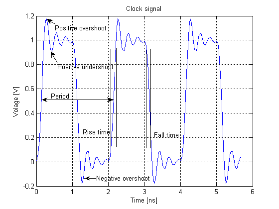
In electronics and especially synchronous digital circuits, a clock signal (historically also known as ''logic beat'') is an electronic logic signal (voltage or current) which oscillates between a high and a low state at a constant frequency and is used like a metronome to synchronize actions of digital circuits. In a synchronous logic circuit, the most common type of digital circuit, the clock signal is applied to all storage devices, flip-flops and latches, and causes them all to change state simultaneously, preventing race conditions. A clock signal is produced by an electronic oscillator called a clock generator. The most common clock signal is in the form of a square wave with a 50% duty cycle. Circuits using the clock signal for synchronization may become active at either the rising edge, falling edge, or, in the case of double data rate, both in the rising and in the falling edges of the clock cycle. Digital circuits Most integrated circuits (ICs) of suffi ... [...More Info...] [...Related Items...] OR: [Wikipedia] [Google] [Baidu] [Amazon] |
Clock Skew
Clock skew (sometimes called timing skew) is a phenomenon in synchronous digital circuit systems (such as computer systems) in which the same sourced clock signal arrives at different components at different times due to gate or, in more advanced semiconductor technology, wire signal propagation delay. The instantaneous difference between the readings of any two clocks is called their skew. The operation of most digital circuits is synchronized by a periodic signal known as a " clock" that dictates the sequence and pacing of the devices on the circuit. This clock is distributed from a single source to all the memory elements of the circuit, which for example could be registers or flip-flops. In a circuit using edge-triggered registers, when the clock edge or tick arrives at a register, the register transfers the register input to the register output, and these new output values flow through combinational logic to provide the values at register inputs for the next clock tic ... [...More Info...] [...Related Items...] OR: [Wikipedia] [Google] [Baidu] [Amazon] |
Duty Cycle
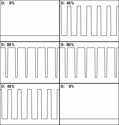
A duty cycle or power cycle is the fraction of one period in which a signal or system is active. Duty cycle is commonly expressed as a percentage or a ratio. A period is the time it takes for a signal to complete an on-and-off cycle. As a formula, a duty cycle (%) may be expressed as: :D = \frac \times 100\% Equally, a duty cycle (ratio) may be expressed as: :D = \frac where D is the duty cycle, PW is the pulse width (pulse active time), and T is the total period of the signal. Thus, a 60% duty cycle means the signal is on 60% of the time and off 40% of the time. The "on time" for a 60% duty cycle could be a fraction of a second, a day, or even a week, depending on the length of the period. Duty cycles can be used to describe the percent time of an active signal in an electrical device such as the power switch in a switching power supply or the firing of action potentials by a living system such as a neuron. Some publications use \alpha as the symbol for duty cycle. As a ... [...More Info...] [...Related Items...] OR: [Wikipedia] [Google] [Baidu] [Amazon] |
Phase Shift
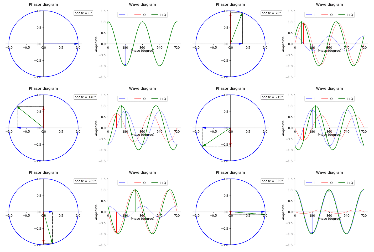
In physics and mathematics, the phase (symbol φ or ϕ) of a wave or other periodic function F of some real variable t (such as time) is an angle-like quantity representing the fraction of the cycle covered up to t. It is expressed in such a scale that it varies by one full turn as the variable t goes through each period (and F(t) goes through each complete cycle). It may be measured in any angular unit such as degrees or radians, thus increasing by 360° or 2\pi as the variable t completes a full period. This convention is especially appropriate for a sinusoidal function, since its value at any argument t then can be expressed as \varphi(t), the sine of the phase, multiplied by some factor (the amplitude of the sinusoid). (The cosine may be used instead of sine, depending on where one considers each period to start.) Usually, whole turns are ignored when expressing the phase; so that \varphi(t) is also a periodic function, with the same period as F, that repeatedly sc ... [...More Info...] [...Related Items...] OR: [Wikipedia] [Google] [Baidu] [Amazon] |
Delay-locked Loop
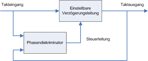
In electronics, a delay-locked loop (DLL) is a pseudo-digital circuit similar to a phase-locked loop (PLL), with the main difference being the absence of an internal voltage-controlled oscillator, replaced by a delay line. A DLL can be used to change the phase of a clock signal (a signal with a periodic waveform), usually to enhance the ''clock rise''-to-''data output valid'' timing characteristics of integrated circuits (such as DRAM devices). DLLs can also be used for clock recovery (CDR). From the outside, a DLL can be seen as a negative delay gate placed in the clock path of a digital circuit. The main component of a DLL is a delay chain composed of many delay gates connected output-to-input. The input of the chain (and thus of the DLL) is connected to the clock that is to be negatively delayed. A multiplexer is connected to each stage of the delay chain; a control circuit automatically updates the selector of this multiplexer to produce the negative delay effect. The output o ... [...More Info...] [...Related Items...] OR: [Wikipedia] [Google] [Baidu] [Amazon] |
Phase-locked Loop
A phase-locked loop or phase lock loop (PLL) is a control system that generates an output signal whose phase is fixed relative to the phase of an input signal. Keeping the input and output phase in lockstep also implies keeping the input and output frequencies the same, thus a phase-locked loop can also track an input frequency. Furthermore, by incorporating a frequency divider, a PLL can generate a stable frequency that is a multiple of the input frequency. These properties are used for clock synchronization, demodulation, frequency synthesis, clock multipliers, and signal recovery from a noisy communication channel. Since 1969, a single integrated circuit can provide a complete PLL building block, and nowadays have output frequencies from a fraction of a hertz up to many gigahertz. Thus, PLLs are widely employed in radio, telecommunications, computers (e.g. to distribute precisely timed clock signals in microprocessors), grid-tie inverters (electronic power converters used ... [...More Info...] [...Related Items...] OR: [Wikipedia] [Google] [Baidu] [Amazon] |
Gate Arrays
A gate or gateway is a point of entry to or from a space enclosed by walls. The word is derived from Proto-Germanic ''*gatan'', meaning an opening or passageway. Synonyms include yett (which comes from the same root word) and portal. The concept originally referred to the gap or hole in the wall or fence, rather than a barrier which closed it. Gates may prevent or control the entry or exit of individuals, or they may be merely decorative. The moving part or parts of a gateway may be considered " doors", as they are fixed at one side whilst opening and closing like one. A gate may have a latch that can be raised and lowered to both open a gate or prevent it from swinging. Gate operation can be either automated or manual. Locks are also used on gates to increase security. Larger gates can be used for a whole building, such as a castle or fortified town. Doors can also be considered gates when they are used to block entry as prevalent within a gatehouse. Purpose-specifi ... [...More Info...] [...Related Items...] OR: [Wikipedia] [Google] [Baidu] [Amazon] |
Electronic Oscillators
An electronic oscillator is an electronic circuit that produces a periodic, oscillating or alternating current (AC) signal, usually a sine wave, square wave or a triangle wave, powered by a direct current (DC) source. Oscillators are found in many electronic devices, such as radio receivers, television sets, radio and television broadcast transmitters, computers, computer peripherals, cellphones, radar, and many other devices. Oscillators are often characterized by the frequency of their output signal: *A low-frequency oscillator (LFO) is an oscillator that generates a frequency below approximately 20 Hz. This term is typically used in the field of audio synthesizers, to distinguish it from an audio frequency oscillator. *An audio oscillator produces frequencies in the audio range, 20 Hz to 20 kHz. *A radio frequency (RF) oscillator produces signals above the audio range, more generally in the range of 100 kHz to 100 GHz. There are two general typ ... [...More Info...] [...Related Items...] OR: [Wikipedia] [Google] [Baidu] [Amazon] |
Integrated Circuits
An integrated circuit (IC), also known as a microchip or simply chip, is a set of electronic circuits, consisting of various electronic components (such as transistors, resistors, and capacitors) and their interconnections. These components are etched onto a small, flat piece ("chip") of semiconductor material, usually silicon. Integrated circuits are used in a wide range of electronic devices, including computers, smartphones, and televisions, to perform various functions such as processing and storing information. They have greatly impacted the field of electronics by enabling device miniaturization and enhanced functionality. Integrated circuits are orders of magnitude smaller, faster, and less expensive than those constructed of discrete components, allowing a large transistor count. The IC's mass production capability, reliability, and building-block approach to integrated circuit design have ensured the rapid adoption of standardized ICs in place of designs using discre ... [...More Info...] [...Related Items...] OR: [Wikipedia] [Google] [Baidu] [Amazon] |
Digital Electronics
Digital electronics is a field of electronics involving the study of digital signals and the engineering of devices that use or produce them. It deals with the relationship between Binary number, binary inputs and outputs by passing electrical signals through Logic gate, logical gates, Resistor, resistors, Capacitor, capacitors, Amplifier, amplifiers, and other Electronic component, electrical components. The field of digital electronics is in contrast to analog electronics which work primarily with analog signals (signals with varying degrees of intensity as opposed to on/off two state binary signals). Despite the name, digital electronics designs include important analog design considerations. Large assemblies of logic gates, used to represent more complex ideas, are often packaged into integrated circuits. Complex devices may have simple electronic representations of Boolean logic#Digital electronic circuit design, Boolean logic functions. History The binary number system was ... [...More Info...] [...Related Items...] OR: [Wikipedia] [Google] [Baidu] [Amazon] |
