|
Common-emitter
In electronics, a common-emitter amplifier is one of three basic single-stage bipolar-junction-transistor (BJT) amplifier topologies, typically used as a voltage amplifier. It offers high current gain (typically 200), medium input resistance and a high output resistance. The output of a common emitter amplifier is 180 degrees out of phase to the input signal. In this circuit the base terminal of the transistor serves as the input, the collector is the output, and the emitter is ''common'' to both (for example, it may be tied to ground reference or a power supply rail), hence its name. The analogous FET circuit is the common-source amplifier, and the analogous tube circuit is the common-cathode amplifier. Emitter degeneration Common-emitter amplifiers give the amplifier an inverted output and can have a very high gain that may vary widely from one transistor to the next. The gain is a strong function of both temperature and bias current, and so the actual gain is somewha ... [...More Info...] [...Related Items...] OR: [Wikipedia] [Google] [Baidu] |
Bipolar Junction Transistor
A bipolar junction transistor (BJT) is a type of transistor that uses both electrons and electron holes as charge carriers. In contrast, a unipolar transistor, such as a field-effect transistor, uses only one kind of charge carrier. A bipolar transistor allows a small current injected at one of its terminals to control a much larger current flowing between the terminals, making the device capable of amplification or switching. BJTs use two p–n junctions between two semiconductor types, n-type and p-type, which are regions in a single crystal of material. The junctions can be made in several different ways, such as changing the doping of the semiconductor material as it is grown, by depositing metal pellets to form alloy junctions, or by such methods as diffusion of n-type and p-type doping substances into the crystal. The superior predictability and performance of junction transistors quickly displaced the original point-contact transistor. Diffused transistors, alon ... [...More Info...] [...Related Items...] OR: [Wikipedia] [Google] [Baidu] |
Common-source
In electronics, a common-source amplifier is one of three basic single-stage field-effect transistor (FET) amplifier topologies, typically used as a voltage or transconductance amplifier. The easiest way to tell if a FET is common source, common drain, or common gate is to examine where the signal enters and leaves. The remaining terminal is what is known as "common". In this example, the signal enters the gate, and exits the drain. The only terminal remaining is the source. This is a common-source FET circuit. The analogous bipolar junction transistor circuit may be viewed as a transconductance amplifier or as a voltage amplifier. (See classification of amplifiers). As a transconductance amplifier, the input voltage is seen as modulating the current going to the load. As a voltage amplifier, input voltage modulates the current flowing through the FET, changing the voltage across the output resistance according to Ohm's law. However, the FET device's output resistance typical ... [...More Info...] [...Related Items...] OR: [Wikipedia] [Google] [Baidu] |
Resistor
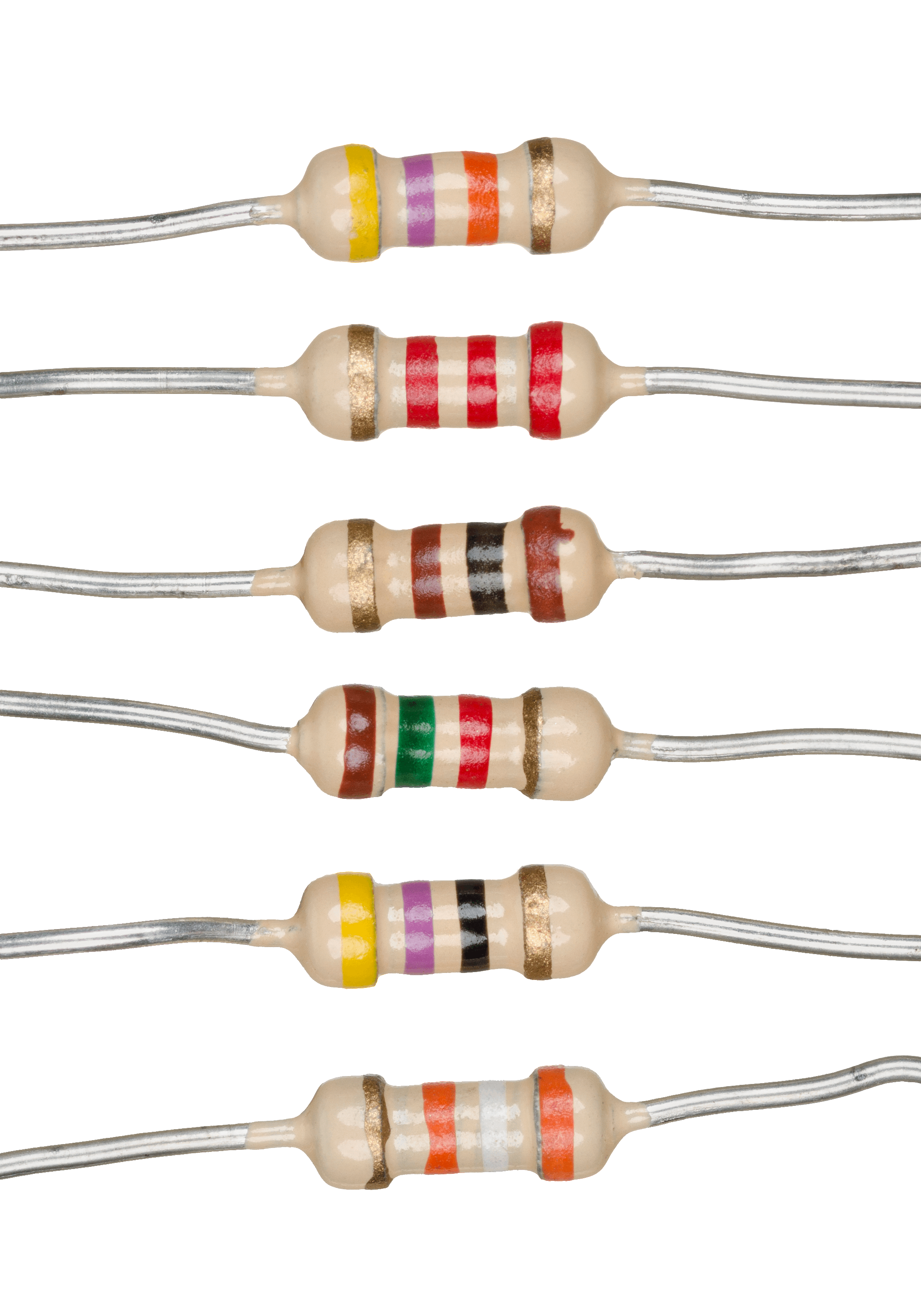
A resistor is a passive two-terminal electrical component that implements electrical resistance as a circuit element. In electronic circuits, resistors are used to reduce current flow, adjust signal levels, to divide voltages, bias active elements, and terminate transmission lines, among other uses. High-power resistors that can dissipate many watts of electrical power as heat may be used as part of motor controls, in power distribution systems, or as test loads for generators. Fixed resistors have resistances that only change slightly with temperature, time or operating voltage. Variable resistors can be used to adjust circuit elements (such as a volume control or a lamp dimmer), or as sensing devices for heat, light, humidity, force, or chemical activity. Resistors are common elements of electrical networks and electronic circuits and are ubiquitous in electronic equipment. Practical resistors as discrete components can be composed of various compounds and forms. R ... [...More Info...] [...Related Items...] OR: [Wikipedia] [Google] [Baidu] |
Time Constant
In physics and engineering, the time constant, usually denoted by the Greek letter (tau), is the parameter characterizing the response to a step input of a first-order, linear time-invariant (LTI) system.Concretely, a first-order LTI system is a system that can be modeled by a single first order differential equation in time. Examples include the simplest single-stage electrical RC circuits and RL circuits. The time constant is the main characteristic unit of a first-order LTI system. In the time domain, the usual choice to explore the time response is through the step response to a step input, or the impulse response to a Dirac delta function input. In the frequency domain (for example, looking at the Fourier transform of the step response, or using an input that is a simple sinusoidal function of time) the time constant also determines the bandwidth of a first-order time-invariant system, that is, the frequency at which the output signal power drops to half the value it has ... [...More Info...] [...Related Items...] OR: [Wikipedia] [Google] [Baidu] |
The Art Of Electronics
''The Art of Electronics'', by Paul Horowitz and Winfield Hill, is a popular reference textbook dealing with analog and digital electronics. The first edition was published in 1980, and the 1989 second edition has been regularly reprinted. The third edition was published on April 9, 2015. The author is accepting reports of errata and publishing them, to be corrected in future revisions. Overview The book covers many areas of circuit design, from basic DC voltage, current, and resistance, to active filters and oscillators, to digital electronics, including microprocessors and digital bus interfacing. It also includes discussions of such often-neglected areas as high-frequency, high-speed design techniques and low- power applications. The book includes many example circuits. In addition to having examples of good circuits, it also has examples of bad ideas, with discussions of what makes the good designs good and the bad ones bad. It can be described as a cross between a textb ... [...More Info...] [...Related Items...] OR: [Wikipedia] [Google] [Baidu] |
Winfield Hill
Winfield Hill is the Director of the Electronics Engineering Laboratory at the Rowland Institute at Harvard University. A self-proclaimed "electronics circuit-design guru" and trained physicist and electronic engineer, he co-authored the popular text '' The Art of Electronics'' with Harvard Physicist Paul Horowitz. Engineering work by Hill in the late 1970s at Harvard led him to found the Sea Data Corporation The sea, connected as the world ocean or simply the ocean, is the body of salty water that covers approximately 71% of the Earth's surface. The word sea is also used to denote second-order sections of the sea, such as the Mediterranean Sea, ..., which designed instruments for deep-sea oceanography. References #Winfield Hill's Electronics/Engineering Home Page External linksWinfield Hill The Rowland Institute at Harvard 21st-century American engineers Harvard University faculty Living people Year of birth missing (living people) Place of birth missing (livi ... [...More Info...] [...Related Items...] OR: [Wikipedia] [Google] [Baidu] |
Paul Horowitz
Paul Horowitz (born 1942) is an American physicist and electrical engineer, known primarily for his work in electronics design, as well as for his role in the search for extraterrestrial intelligence (see SETI). Biography At age 8, Horowitz achieved distinction as the world's youngest amateur radio operator. He went on to study physics at Harvard University ( B.A., 1965; M.A., 1967; Ph.D., 1970), where he has also spent all of his subsequent career. His early work was on scanning microscopy (using both protons and X-rays). Horowitz has also conducted astrophysical research on pulsars and investigations in biophysics. His interest in practical electronics has led to a handful of inventions, including an automated voting machine and an acoustic mechanism for landmine detection, and an electronic Morse Code/Baudot code keyboard using a diode matrix and 66 TTL integrated circuits for Amateur Radio use. Since 1974 he has taught a practical course in electronics whose l ... [...More Info...] [...Related Items...] OR: [Wikipedia] [Google] [Baidu] |
Parasitic Capacitance
Parasitic capacitance is an unavoidable and usually unwanted capacitance that exists between the parts of an electronic component or circuit simply because of their proximity to each other. When two electrical conductors at different voltages are close together, the electric field between them causes electric charge to be stored on them; this effect is capacitance. All practical circuit elements such as inductors, diodes, and transistors have internal capacitance, which can cause their behavior to depart from that of ideal circuit elements. Additionally, there is always non-zero capacitance between any two conductors; this can be significant with closely spaced conductors, such as wires or printed circuit board traces. The parasitic capacitance between the turns of an inductor or other wound component is often described as ''self-capacitance''. However, in electromagnetics, the term self-capacitance more correctly refers to a different phenomenon: the capacitance of a ... [...More Info...] [...Related Items...] OR: [Wikipedia] [Google] [Baidu] |
Miller Effect
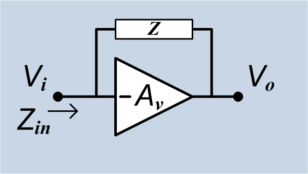
In electronics, the Miller effect accounts for the increase in the equivalent input capacitance of an inverting voltage amplifier due to amplification of the effect of capacitance between the input and output terminals. The virtually increased input capacitance due to the Miller effect is given by :C_=C (1+A_v)\, where -A_v is the voltage gain of the inverting amplifier (A_v positive) and C is the feedback capacitance. Although the term ''Miller effect'' normally refers to capacitance, any impedance connected between the input and another node exhibiting gain can modify the amplifier input impedance via this effect. These properties of the Miller effect are generalized in the Miller theorem. The Miller capacitance due to parasitic capacitance between the output and input of active devices like transistors and vacuum tubes is a major factor limiting their gain at high frequencies. Miller capacitance was identified in 1920 in triode vacuum tubes by John Milton Miller. History ... [...More Info...] [...Related Items...] OR: [Wikipedia] [Google] [Baidu] |
Output Impedance
The output impedance of an electrical network is the measure of the opposition to current flow (impedance), both static (resistance) and dynamic ( reactance), into the load network being connected that is ''internal'' to the electrical source. The output impedance is a measure of the source's propensity to drop in voltage when the load draws current, the source network being the portion of the network that transmits and the load network being the portion of the network that consumes. Because of this the output impedance is sometimes referred to as the source impedance or internal impedance. Description All devices and connections have non-zero resistance and reactance, and therefore no device can be a perfect source. The output impedance is often used to model the source's response to current flow. Some portion of the device's measured output impedance may not physically exist within the device; some are artifacts that are due to the chemical, thermodynamic, or mechanical prope ... [...More Info...] [...Related Items...] OR: [Wikipedia] [Google] [Baidu] |
Input Impedance
The input impedance of an electrical network is the measure of the opposition to current ( impedance), both static (resistance) and dynamic ( reactance), into the load network that is ''external'' to the electrical source. The input admittance (the reciprocal of impedance) is a measure of the load's propensity to draw current. The source network is the portion of the network that transmits power, and the load network is the portion of the network that consumes power. Input impedance If the load network were replaced by a device with an output impedance equal to the input impedance of the load network (equivalent circuit), the characteristics of the source-load network would be the same from the perspective of the connection point. So, the voltage across and the current through the input terminals would be identical to the chosen load network. Therefore, the input impedance of the load and the output impedance of the source determine how the source current and voltage change. T ... [...More Info...] [...Related Items...] OR: [Wikipedia] [Google] [Baidu] |

