|
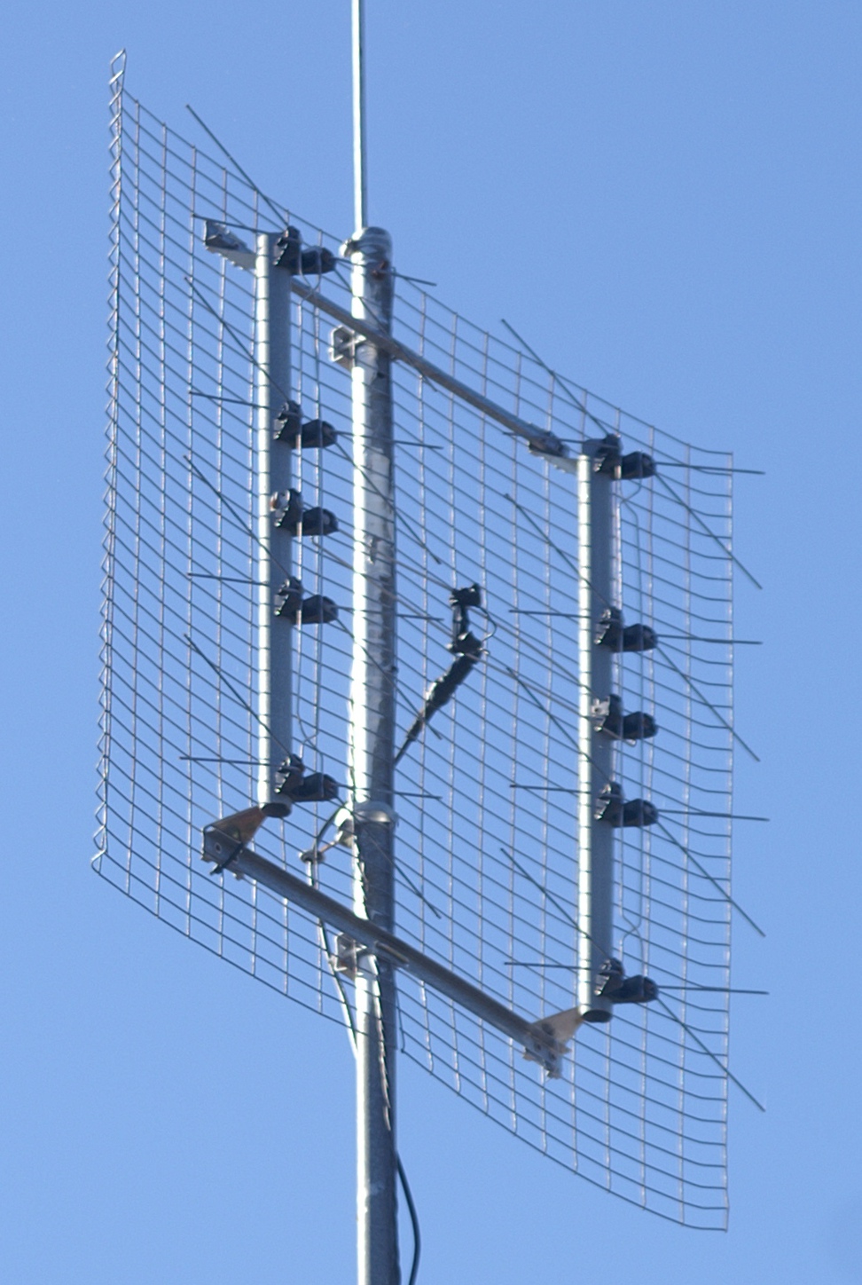
Reflective Array Antenna
In telecommunications and radar, a reflective array antenna is a class of directive antennas in which multiple driven elements are mounted in front of a flat surface designed to reflect the radio waves in a desired direction. They are a type of array antenna. They are often used in the VHF and UHF frequency bands. VHF examples are generally large and resemble a highway billboard, so they are sometimes called billboard antennas. Other names are bedspring array and bowtie array depending on the type of elements making up the antenna. The curtain array is a larger version used by shortwave radio broadcasting stations. Reflective array antennas usually have a number of identical driven elements, fed in phase, in front of a flat, electrically large reflecting surface to produce a unidirectional beam of radio waves, increasing antenna gain and reducing radiation in unwanted directions. The larger the number of elements used, the higher the gain; the narrower the beam is an ... [...More Info...] [...Related Items...] OR: [Wikipedia] [Google] [Baidu] |
Eight Bay Bowtie TV Antenna
8 is a number, numeral, and glyph. 8 or eight may also refer to: Years * AD 8, the eighth year of the AD era * 8 BC, the eighth year before the AD era Art *The Eight (Ashcan School), a group of twentieth century painters associated with the Ashcan School *The Eight (painters), an avant-garde art movement of Hungarian painters Motor vehicles *Bentley Eight, Bentley's "entry-level" offering from 1984 until 1992 * Leyland Eight, a luxury car produced by Leyland Motors from 1920 to 1923 *Mercury Eight, a first Post War Mercury car design *Morris Eight, a small car inspired by the Ford Model Y *Standard Eight, a small car produced by Standard Motor Company 1938–59 *Wolseley Eight, a four-door, light saloon car produced by Wolseley Motors Limited from 1946 to 1948 *Straight eight, automobile engine *Eight cylinder, automobile engine Sports * Eight (rowing), rowing boat used in the sport of competitive rowing *Figure 8 (belay device), rock climbing equipment also known as an "eig ... [...More Info...] [...Related Items...] OR: [Wikipedia] [Google] [Baidu] |
Radiation
In physics, radiation is the emission or transmission of energy in the form of waves or particles through space or through a material medium. This includes: * ''electromagnetic radiation'', such as radio waves, microwaves, infrared, visible light, ultraviolet, x-rays, and gamma radiation (γ) * ''particle radiation'', such as alpha radiation (α), beta radiation (β), proton radiation and neutron radiation (particles of non-zero rest energy) * '' acoustic radiation'', such as ultrasound, sound, and seismic waves (dependent on a physical transmission medium) * ''gravitational wave, gravitational radiation'', that takes the form of gravitational waves, or ripples in the curvature of spacetime Radiation is often categorized as either ''ionizing radiation, ionizing'' or ''non-ionizing radiation, non-ionizing'' depending on the energy of the radiated particles. Ionizing radiation carries more than 10 electron volt, eV, which is enough to ionize atoms and molecules and break ... [...More Info...] [...Related Items...] OR: [Wikipedia] [Google] [Baidu] |
Bowtie Antenna
In radio systems, a biconical antenna is a broad-bandwidth antenna made of two roughly conical conductive objects, nearly touching at their points.Zhuohui Zhang,''Analysis and design of a broadband antenna for software defined radio'', ProQuest, 2007 , page 6 Biconical antennas are broadband dipole antennas, typically exhibiting a bandwidth of three octaves or more. A common subtype is the bowtie antenna, essentially a two-dimensional version of the biconial design which is often used for short-range UHF television reception. These are also sometimes referred to as butterfly antennas. Properties The biconical antenna has a broad bandwidth because it is an example of a traveling wave structure; the analysis for a theoretical infinite antenna resembles that of a transmission line. For an infinite antenna, the characteristic impedance at the point of connection is a function of the cone angle only and is independent of the frequency. Practical antennas have finite length and a d ... [...More Info...] [...Related Items...] OR: [Wikipedia] [Google] [Baidu] |
Front-to-back Ratio
In telecommunication, the term front-to-back ratio (''also known as front-to-rear ratio'') can mean: #The ratio of power gain between the front and rear of a directional antenna. #Ratio of signal strength transmitted in a forward direction to that transmitted in a backward direction. For receiving antennas, the ratio of received-signal strength when the antenna is rotated 180°.Radio Shack 1974-75 unabridged Dictionary of Electronics edited by Rudolf F. Graf, cat. no. 68-1030 The ratio compares the antenna gain in a specified direction, ''i.e.'', azimuth, usually that of maximum gain, to the gain in a direction 180° from the specified azimuth. A front-to-back ratio is usually expressed in dB. In point-to-point microwave antennas, a "high performance" antenna usually has a higher front to back ratio than other antennas. For example, an unshrouded 38 GHz microwave dish may have a front to back ratio of 64 dB, while the same size reflector equipped with a shroud would have a fr ... [...More Info...] [...Related Items...] OR: [Wikipedia] [Google] [Baidu] |
Television Antenna
A television antenna (TV aerial) is an antenna specifically designed for use with a television receiver (TV) to receive over-the-air broadcast television signals from a television station. Television reception is dependent upon the antenna as well as the transmitter. Terrestrial television is broadcast on frequencies from about 47 to 250 MHz in the very high frequency (VHF) band, and 470 to 960 MHz in the ultra high frequency (UHF) band in different countries. Television antennas are manufactured in two different types: "indoor" antennas, to be located on top of or next to the television set, and "outdoor" antennas, mounted on a mast on top of the owner's house.Johnson 1993 Antenna Engineering Handbook, 3rd Ed.', p. 29.5-29.6 They can also be mounted in a loft or attic, where the dry conditions and increased elevation are advantageous for reception and antenna longevity. Outdoor antennas are more expensive and difficult to install, but are necessary for adequate r ... [...More Info...] [...Related Items...] OR: [Wikipedia] [Google] [Baidu] |
Antenna Gain
In electromagnetics, an antenna's gain is a key performance parameter which combines the antenna's directivity and radiation efficiency. The term ''power gain'' has been deprecated by IEEE. In a transmitting antenna, the gain describes how well the antenna converts input power into radio waves headed in a specified direction. In a receiving antenna, the gain describes how well the antenna converts radio waves arriving from a specified direction into electrical power. When no direction is specified, gain is understood to refer to the peak value of the gain, the gain in the direction of the antenna's main lobe. A plot of the gain as a function of direction is called the antenna pattern or radiation pattern. It is not to be confused with directivity, which does ''not'' take an antenna's radiation efficiency into account. Gain or 'absolute gain' is defined as "The ratio of the radiation intensity in a given direction to the radiation intensity that would be produced if the p ... [...More Info...] [...Related Items...] OR: [Wikipedia] [Google] [Baidu] |
Dipole Antenna
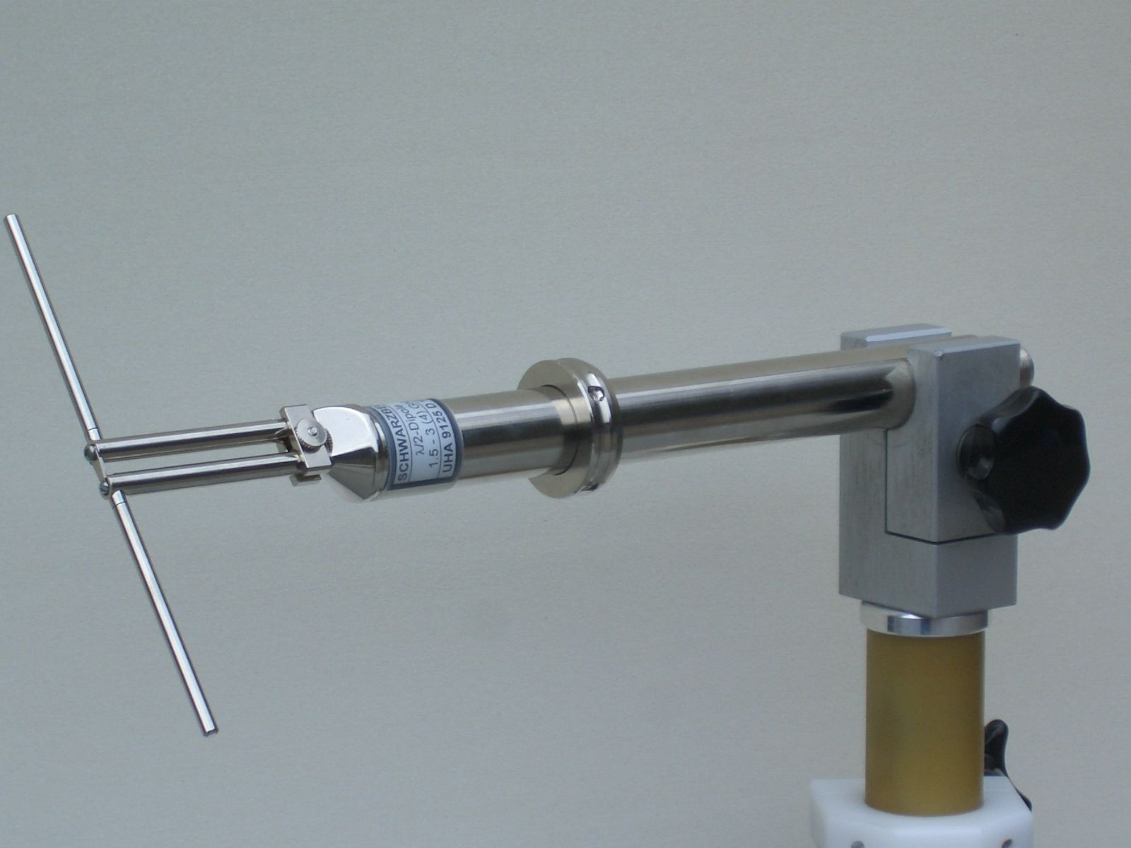
In radio and telecommunications a dipole antenna or doublet is the simplest and most widely used class of antenna. The dipole is any one of a class of antennas producing a radiation pattern approximating that of an elementary electric dipole with a radiating structure supporting a line current so energized that the current has only one node at each end. A dipole antenna commonly consists of two identical conductive elements such as metal wires or rods. The driving current from the transmitter is applied, or for receiving antennas the output signal to the receiver is taken, between the two halves of the antenna. Each side of the feedline to the transmitter or receiver is connected to one of the conductors. This contrasts with a monopole antenna, which consists of a single rod or conductor with one side of the feedline connected to it, and the other side connected to some type of ground. A common example of a dipole is the "rabbit ears" television antenna found on broadcast telev ... [...More Info...] [...Related Items...] OR: [Wikipedia] [Google] [Baidu] |
Phase (waves)
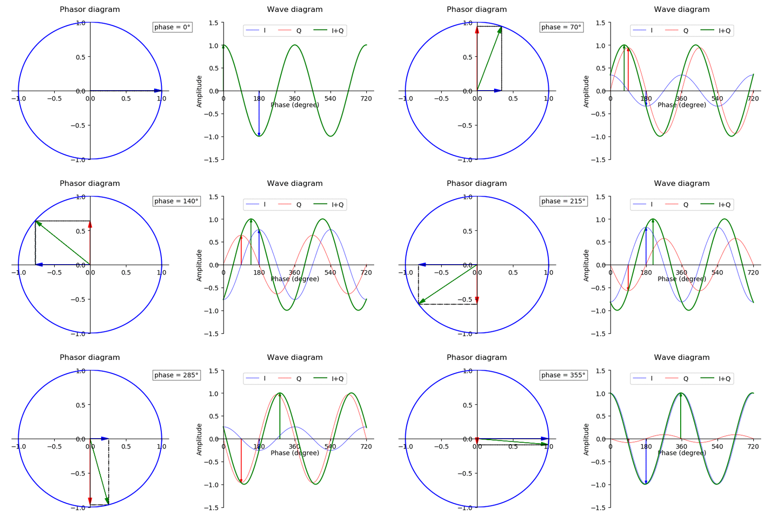
In physics and mathematics, the phase of a periodic function F of some real variable t (such as time) is an angle-like quantity representing the fraction of the cycle covered up to t. It is denoted \phi(t) and expressed in such a scale that it varies by one full turn as the variable t goes through each period (and F(t) goes through each complete cycle). It may be measured in any angular unit such as degrees or radians, thus increasing by 360° or 2\pi as the variable t completes a full period. This convention is especially appropriate for a sinusoidal function, since its value at any argument t then can be expressed as \phi(t), the sine of the phase, multiplied by some factor (the amplitude of the sinusoid). (The cosine may be used instead of sine, depending on where one considers each period to start.) Usually, whole turns are ignored when expressing the phase; so that \phi(t) is also a periodic function, with the same period as F, that repeatedly scans the same range of ... [...More Info...] [...Related Items...] OR: [Wikipedia] [Google] [Baidu] |
Antenna Array (electromagnetic)
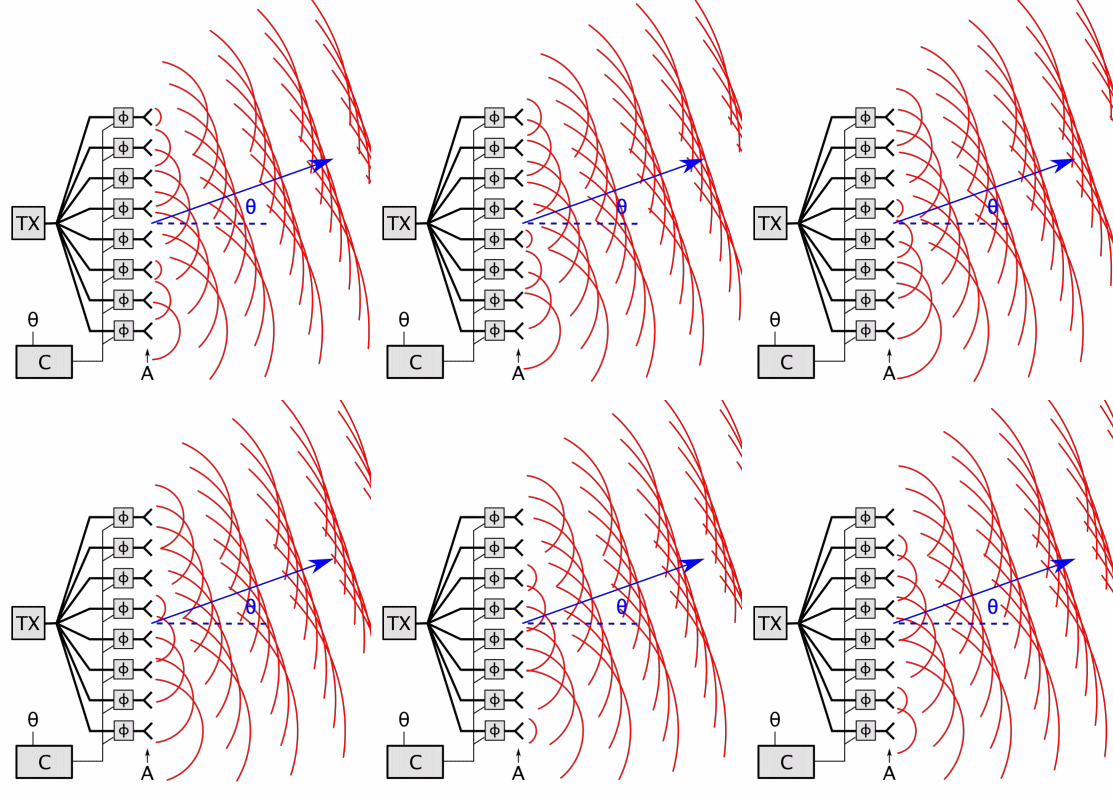
An antenna array (or array antenna) is a set of multiple connected antennas which work together as a single antenna, to transmit or receive radio waves. The individual antennas (called ''elements'') are usually connected to a single receiver or transmitter by feedlines that feed the power to the elements in a specific phase relationship. The radio waves radiated by each individual antenna combine and superpose, adding together ( interfering constructively) to enhance the power radiated in desired directions, and cancelling ( interfering destructively) to reduce the power radiated in other directions. Similarly, when used for receiving, the separate radio frequency currents from the individual antennas combine in the receiver with the correct phase relationship to enhance signals received from the desired directions and cancel signals from undesired directions. More sophisticated array antennas may have multiple transmitter or receiver modules, each connected to a separate a ... [...More Info...] [...Related Items...] OR: [Wikipedia] [Google] [Baidu] |
Standing Wave
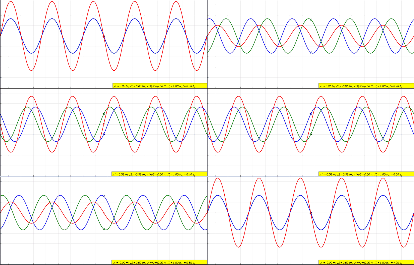
In physics, a standing wave, also known as a stationary wave, is a wave that oscillates in time but whose peak amplitude profile does not move in space. The peak amplitude of the wave oscillations at any point in space is constant with respect to time, and the oscillations at different points throughout the wave are in phase. The locations at which the absolute value of the amplitude is minimum are called nodes, and the locations where the absolute value of the amplitude is maximum are called antinodes. Standing waves were first noticed by Michael Faraday in 1831. Faraday observed standing waves on the surface of a liquid in a vibrating container. Franz Melde coined the term "standing wave" (German: ''stehende Welle'' or ''Stehwelle'') around 1860 and demonstrated the phenomenon in his classic experiment with vibrating strings. This phenomenon can occur because the medium is moving in the direction opposite to the movement of the wave, or it can arise in a stationary medium ... [...More Info...] [...Related Items...] OR: [Wikipedia] [Google] [Baidu] |
Electromagnetic Induction
Electromagnetic or magnetic induction is the production of an electromotive force (emf) across an electrical conductor in a changing magnetic field. Michael Faraday is generally credited with the discovery of induction in 1831, and James Clerk Maxwell mathematically described it as Faraday's law of induction. Lenz's law describes the direction of the induced field. Faraday's law was later generalized to become the Maxwell–Faraday equation, one of the four Maxwell equations in his theory of electromagnetism. Electromagnetic induction has found many applications, including electrical components such as inductors and transformers, and devices such as electric motors and generators. History Electromagnetic induction was discovered by Michael Faraday, published in 1831. It was discovered independently by Joseph Henry in 1832. In Faraday's first experimental demonstration (August 29, 1831), he wrapped two wires around opposite sides of an iron ring or "torus" (an arrangement ... [...More Info...] [...Related Items...] OR: [Wikipedia] [Google] [Baidu] |
Transmission Line
In electrical engineering, a transmission line is a specialized cable or other structure designed to conduct electromagnetic waves in a contained manner. The term applies when the conductors are long enough that the wave nature of the transmission must be taken into account. This applies especially to radio-frequency engineering because the short wavelengths mean that wave phenomena arise over very short distances (this can be as short as millimetres depending on frequency). However, the theory of transmission lines was historically developed to explain phenomena on very long telegraph lines, especially submarine telegraph cables. Transmission lines are used for purposes such as connecting radio transmitters and receivers with their antennas (they are then called feed lines or feeders), distributing cable television signals, trunklines routing calls between telephone switching centres, computer network connections and high speed computer data buses. RF engineers commonly ... [...More Info...] [...Related Items...] OR: [Wikipedia] [Google] [Baidu] |
