|
Reflectional Receiver
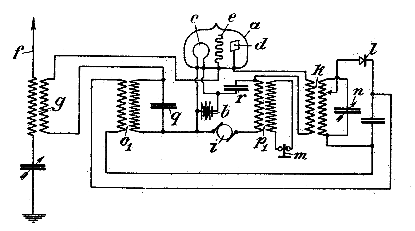
A reflex radio receiver, occasionally called a reflectional receiver, is a radio receiver design in which the same amplifier is used to amplify the high-frequency radio signal (RF) and low-frequency audio (sound) signal (AF). It was first invented in 1914 by German scientists Wilhelm Schloemilch and Otto von Bronk,US Patent no. 1087892, Wilhelm Schloemilch and Otto von Bronk Means for receiving electrical oscillations', filed March 14, 1913; granted February 17, 1914 and rediscovered and extended to multiple tubes in 1917 by Marius LatourUS Patent no. 1405523, Marius Latour Audion or lamp relay or amplifying apparatus', filed December 28, 1917; granted February 7, 1922 and William H. Priess. The radio signal from the antenna and tuned circuit passes through an amplifier, is demodulated in a detector which extracts the audio signal from the radio carrier, and the resulting audio signal passes ''again'' through the same amplifier for audio amplification before being applied to the e ... [...More Info...] [...Related Items...] OR: [Wikipedia] [Google] [Baidu] |
Regenerative Receiver
A regenerative circuit is an amplifier circuit that employs positive feedback (also known as regeneration or reaction). Some of the output of the amplifying device is applied back to its input so as to add to the input signal, increasing the amplification. One example is the Schmitt trigger (which is also known as a regenerative comparator), but the most common use of the term is in Radio Frequency, RF amplifiers, and especially regenerative receivers, to greatly increase the gain (electronics), gain of a single amplifier stage. The regenerative receiver was invented in 1912 and patented in 1914US Patent 1113149A, Edwin H. Armstrong, Wireless receiving system', filed October 29, 1913, granted October 6, 1914 by American electrical engineer Edwin Armstrong when he was an undergraduate at Columbia University. It was widely used between 1915 and World War II. Advantages of regenerative receivers include increased sensitivity with modest hardware requirements, and increased selec ... [...More Info...] [...Related Items...] OR: [Wikipedia] [Google] [Baidu] |
Triode
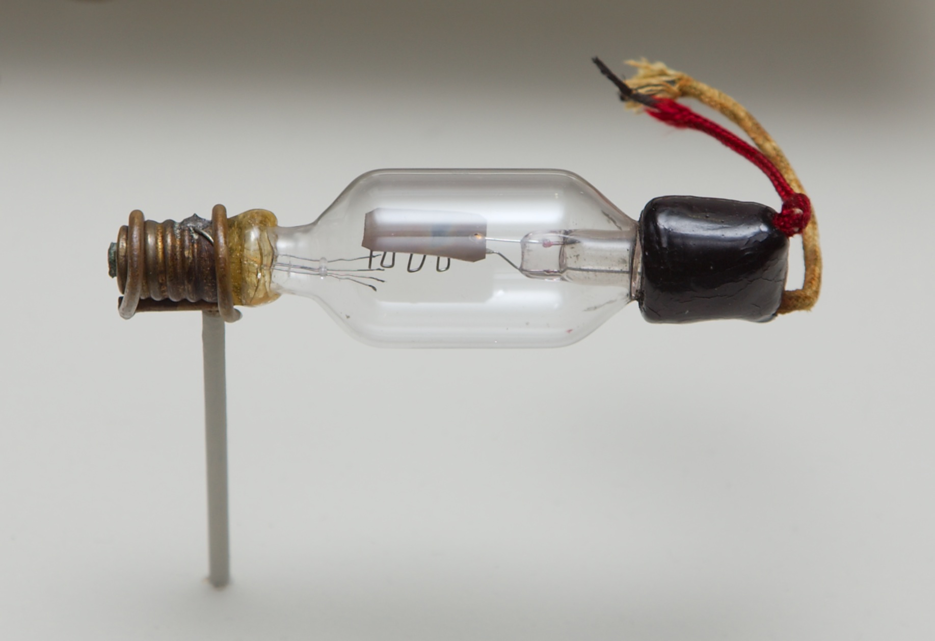
A triode is an electronic amplifying vacuum tube (or ''valve'' in British English) consisting of three electrodes inside an evacuated glass envelope: a heated filament or cathode, a grid, and a plate (anode). Developed from Lee De Forest's 1906 Audion, a partial vacuum tube that added a grid electrode to the thermionic diode (Fleming valve), the triode was the first practical electronic amplifier and the ancestor of other types of vacuum tubes such as the tetrode and pentode. Its invention founded the electronics age, making possible amplified radio technology and long-distance telephony. Triodes were widely used in consumer electronics devices such as radios and televisions until the 1970s, when transistors replaced them. Today, their main remaining use is in high-power RF amplifiers in radio transmitters and industrial RF heating devices. In recent years there has been a resurgence in demand for low power triodes due to renewed interest in tube-type audio systems by audiophi ... [...More Info...] [...Related Items...] OR: [Wikipedia] [Google] [Baidu] |
Single Tube Reflex Receiver Circuit
Single may refer to: Arts, entertainment, and media * Single (music), a song release Songs * "Single" (Natasha Bedingfield song), 2004 * "Single" (New Kids on the Block and Ne-Yo song), 2008 * "Single" (William Wei song), 2016 * "Single", by Meghan Trainor from the album '' Only 17'' Sports * Single (baseball), the most common type of base hit * Single (cricket), point in cricket * Single (football), Canadian football point * Single-speed bicycle Transportation * Single-cylinder engine, an internal combustion engine design with one cylinder, or a motorcycle using such engine * Single (locomotive), a steam locomotive with a single pair of driving wheels * As a verb: to convert a double-track railway to a single-track railway Other uses * Single (mathematics) (1-tuple), a list or sequence with only one element * Single person, a person who is not in a committed relationship * Single precision, a computer numbering format that occupies one storage location in computer memory at ... [...More Info...] [...Related Items...] OR: [Wikipedia] [Google] [Baidu] |
Intermediate-frequency Amplifier
Intermediate-frequency (IF) amplifiers are amplifier stages used to raise signal levels in radio and television receivers, at frequencies intermediate to the higher radio-frequency (RF) signal from the antenna and the lower (baseband) audio or video frequency that the receiver is recovering. Uses IF amplifiers in heterodyne receivers apply gain in a frequency band between the input radio frequency and output audio frequency or video frequency, often following one stage of RF amplifier. This allows most of the gain in the form of a fixed-frequency amplifier, simplifying tuning. Compare to its predecessor, the tuned RF receiver. IF amplifiers might use double-tuned amplifiers or staggered tuning Staggered tuning is a technique used in the design of multi-stage tuned amplifiers whereby each stage is tuned to a slightly different frequency. In comparison to synchronous tuning (where each stage is tuned identically) it produces a wider Band ... to generate the appropriate freque ... [...More Info...] [...Related Items...] OR: [Wikipedia] [Google] [Baidu] |
Superheterodyne
A superheterodyne receiver, often shortened to superhet, is a type of radio receiver that uses frequency mixing to convert a received signal to a fixed intermediate frequency (IF) which can be more conveniently processed than the original carrier frequency. It was long believed to have been invented by US engineer Edwin Armstrong, but after some controversy the earliest patent for the invention is now credited to French radio engineer and radio manufacturer Lucien Lévy. Virtually all modern radio receivers use the superheterodyne principle; except those software-defined radios using ''direct sampling''. History Heterodyne Early Morse code radio broadcasts were produced using an alternator connected to a spark gap. The output signal was at a carrier frequency defined by the physical construction of the gap, modulated by the alternating current signal from the alternator. Since the output frequency of the alternator was generally in the audible range, this produces an audible a ... [...More Info...] [...Related Items...] OR: [Wikipedia] [Google] [Baidu] |
Tuned Radio Frequency
A tuned radio frequency receiver (or TRF receiver) is a type of radio receiver that is composed of one or more tuned radio frequency (RF) amplifier stages followed by a detector ( demodulator) circuit to extract the audio signal and usually an audio frequency amplifier. This type of receiver was popular in the 1920s. Early examples could be tedious to operate because when tuning in a station each stage had to be individually adjusted to the station's frequency, but later models had ganged tuning, the tuning mechanisms of all stages being linked together, and operated by just one control knob. By the mid 1930s, it was replaced by the superheterodyne receiver patented by Edwin Armstrong. Background The TRF receiver was patented in 1916 by Ernst Alexanderson. His concept was that each stage would amplify the desired signal while reducing the interfering ones. Multiple stages of RF amplification would make the radio more sensitive to weak stations, and the multiple tuned ci ... [...More Info...] [...Related Items...] OR: [Wikipedia] [Google] [Baidu] |
Grid-leak Detector
A grid leak detector is an electronic circuit that demodulates an amplitude modulated alternating current and amplifies the recovered modulating voltage. The circuit utilizes the non-linear cathode to control grid conduction characteristic and the amplification factor of a vacuum tube.H. A. Robinson, "The Operating Characteristics of Vacuum Tube Detectors", Part I, ''QST'', vol. XIV, no. 8, p. 23, Aug. 1930 Invented by Lee De Forest around 1912, it was used as the detector (demodulator) in the first vacuum tube radio receivers until the 1930s. History Early applications of triode tubes (''Audions'') as detectors usually did not include a resistor in the grid circuit. First use of a resistance in the grid circuit of a vacuum tube detector circuit may have been by Sewall Cabot in 1906. Cabot wrote that he made a pencil mark to discharge the grid condenser, after finding that touching the grid terminal of the tube would cause the detector to resume operation after having stoppe ... [...More Info...] [...Related Items...] OR: [Wikipedia] [Google] [Baidu] |
Diode
A diode is a two-terminal electronic component that conducts current primarily in one direction (asymmetric conductance); it has low (ideally zero) resistance in one direction, and high (ideally infinite) resistance in the other. A diode vacuum tube or thermionic diode is a vacuum tube with two electrodes, a heated cathode and a plate, in which electrons can flow in only one direction, from cathode to plate. A semiconductor diode, the most commonly used type today, is a crystalline piece of semiconductor material with a p–n junction connected to two electrical terminals. Semiconductor diodes were the first semiconductor electronic devices. The discovery of asymmetric electrical conduction across the contact between a crystalline mineral and a metal was made by German physicist Ferdinand Braun in 1874. Today, most diodes are made of silicon, but other semiconducting materials such as gallium arsenide and germanium are also used. Among many uses, diodes are found in ... [...More Info...] [...Related Items...] OR: [Wikipedia] [Google] [Baidu] |
Parasitic Oscillation
Parasitic oscillation is an undesirable electronic oscillation (cyclic variation in output voltage or current) in an electronic or digital device. It is often caused by feedback in an amplifying device. The problem occurs notably in RF, audio, and other electronic amplifiers as well as in digital signal processing. It is one of the fundamental issues addressed by control theory. Parasitic oscillation is undesirable for several reasons. The oscillations may be coupled into other circuits or radiate as radio waves, causing electromagnetic interference (EMI) to other devices. In audio systems, parasitic oscillations can sometimes be heard as annoying sounds in the speakers or earphones. The oscillations waste power and may cause undesirable heating. For example, an audio power amplifier that goes into parasitic oscillation may generate enough power to damage connected speakers. A circuit that is oscillating will not amplify linearly, so desired signals passing through the stage will ... [...More Info...] [...Related Items...] OR: [Wikipedia] [Google] [Baidu] |
Feedback
Feedback occurs when outputs of a system are routed back as inputs as part of a chain of cause-and-effect that forms a circuit or loop. The system can then be said to ''feed back'' into itself. The notion of cause-and-effect has to be handled carefully when applied to feedback systems: History Self-regulating mechanisms have existed since antiquity, and the idea of feedback had started to enter economic theory in Britain by the 18th century, but it was not at that time recognized as a universal abstraction and so did not have a name. The first ever known artificial feedback device was a float valve, for maintaining water at a constant level, invented in 270 BC in Alexandria, Egypt. This device illustrated the principle of feedback: a low water level opens the valve, the rising water then provides feedback into the system, closing the valve when the required level is reached. This then reoccurs in a circular fashion as the water level fluctuates. Centrifugal governors were ... [...More Info...] [...Related Items...] OR: [Wikipedia] [Google] [Baidu] |
Intermodulation Distortion
Intermodulation (IM) or intermodulation distortion (IMD) is the amplitude modulation of signals containing two or more different frequencies, caused by nonlinearities or time variance in a system. The intermodulation between frequency components will form additional components at frequencies that are not just at harmonic frequencies (integer multiples) of either, like harmonic distortion, but also at the sum and difference frequencies of the original frequencies and at sums and differences of multiples of those frequencies. Intermodulation is caused by non-linear behaviour of the signal processing (physical equipment or even algorithms) being used. The theoretical outcome of these non-linearities can be calculated by generating a Volterra series of the characteristic, or more approximately by a Taylor series. Practically all audio equipment has some non-linearity, so it will exhibit some amount of IMD, which however may be low enough to be imperceptible by humans. Due t ... [...More Info...] [...Related Items...] OR: [Wikipedia] [Google] [Baidu] |


