|
Phase Shift Oscillator
A phase-shift oscillator is a linear electronic oscillator circuit that produces a sine wave output. It consists of an inverting amplifier element such as a transistor or op amp with its output fed back to its input through a phase-shift network consisting of resistors and capacitors in a ladder network. The feedback network 'shifts' the phase of the amplifier output by 180 degrees at the oscillation frequency to give positive feedback. Phase-shift oscillators are often used at audio frequency as audio oscillators. The filter produces a phase shift that increases with frequency. It must have a maximum phase shift of more than 180 degrees at high frequencies so the phase shift at the desired oscillation frequency can be 180 degrees. The most common phase-shift network cascades three identical resistor-capacitor stages that produce a phase shift of zero at low frequencies and 270° at high frequencies. The first integrated circuit was a phase shift oscillator invented by Jack Kilby ... [...More Info...] [...Related Items...] OR: [Wikipedia] [Google] [Baidu] |
Linear Circuit
A linear circuit is an electronic circuit which obeys the superposition principle. This means that the output of the circuit ''F(x)'' when a linear combination of signals ''ax1(t) + bx2(t)'' is applied to it is equal to the linear combination of the outputs due to the signals ''x1(t)'' and ''x2(t)'' applied separately: :F(ax_1 + bx_2) = aF(x_1) + bF(x_2)\, It is called a linear circuit because the output voltage and current of such a circuit are linear functions of its input voltage and current. This kind of linearity is not the same as that of straight-line graphs. In the common case of a circuit in which the components' values are constant and don't change with time, an alternate definition of linearity is that when a sinusoidal input voltage or current of frequency ''f'' is applied, any steady-state output of the circuit (the current through any component, or the voltage between any two points) is also sinusoidal with frequency ''f''. A linear circuit with constant comp ... [...More Info...] [...Related Items...] OR: [Wikipedia] [Google] [Baidu] |
Cutoff Frequency
In physics and electrical engineering, a cutoff frequency, corner frequency, or break frequency is a boundary in a system's frequency response at which energy flowing through the system begins to be reduced ( attenuated or reflected) rather than passing through. Typically in electronic systems such as filters and communication channels, cutoff frequency applies to an edge in a lowpass, highpass, bandpass, or band-stop characteristic – a frequency characterizing a boundary between a passband and a stopband. It is sometimes taken to be the point in the filter response where a transition band and passband meet, for example, as defined by a half-power point (a frequency for which the output of the circuit is −3 Decibel, dB of the nominal passband value). Alternatively, a stopband corner frequency may be specified as a point where a transition band and a stopband meet: a frequency for which the attenuation is larger than the required stopband attenuation, which for example ... [...More Info...] [...Related Items...] OR: [Wikipedia] [Google] [Baidu] |
Loop Gain
In electronics and control system theory, loop gain is the sum of the gain, expressed as a ratio or in decibels, around a feedback loop. Feedback loops are widely used in electronics in amplifiers and oscillators, and more generally in both electronic and nonelectronic industrial control systems to control industrial plant and equipment. The concept is also used in biology. In a feedback loop, the output of a device, process or plant is sampled and applied to alter the input, to better control the output. The loop gain, along with the related concept of loop phase shift, determines the behavior of the device, and particularly whether the output is stable, or unstable, which can result in oscillation. The importance of loop gain as a parameter for characterizing electronic feedback amplifiers was first recognized by Heinrich Barkhausen in 1921, and was developed further by Hendrik Wade Bode and Harry Nyquist at Bell Labs in the 1930s. A block diagram of an electronic amplifie ... [...More Info...] [...Related Items...] OR: [Wikipedia] [Google] [Baidu] |
Transient (oscillation)
In electrical engineering and mechanical engineering, a transient response is the response of a system to a change from an equilibrium or a steady state. The transient response is not necessarily tied to abrupt events but to any event that affects the equilibrium of the system. The impulse response and step response are transient responses to a specific input (an impulse and a step, respectively). In electrical engineering specifically, the transient response is the circuit’s temporary response that will die out with time. It is followed by the steady state response, which is the behavior of the circuit a long time after an external excitation is applied. Damping The response can be classified as one of three types of damping that describes the output in relation to the steady-state response. ;Underdamped :An underdamped response is one that oscillates within a decaying envelope. The more underdamped the system, the more oscillations and longer it takes to reach steady-stat ... [...More Info...] [...Related Items...] OR: [Wikipedia] [Google] [Baidu] |
Electrical Noise
In electronics, noise is an unwanted disturbance in an electrical signal. Noise generated by electronic devices varies greatly as it is produced by several different effects. In particular, noise is inherent in physics, and central to thermodynamics. Any conductor with electrical resistance will generate thermal noise inherently. The final elimination of thermal noise in electronics can only be achieved cryogenically, and even then quantum noise would remain inherent. Electronic noise is a common component of noise in signal processing. In communication systems, noise is an error or undesired random disturbance of a useful information signal in a communication channel. The noise is a summation of unwanted or disturbing energy from natural and sometimes man-made sources. Noise is, however, typically distinguished from interference, for example in the signal-to-noise ratio (SNR), signal-to-interference ratio (SIR) and signal-to-noise plus interference ratio (SNIR) measu ... [...More Info...] [...Related Items...] OR: [Wikipedia] [Google] [Baidu] |
Negative Feedback
Negative feedback (or balancing feedback) occurs when some function (Mathematics), function of the output of a system, process, or mechanism is feedback, fed back in a manner that tends to reduce the fluctuations in the output, whether caused by changes in the input or by other disturbances. Whereas positive feedback tends to lead to instability via exponential growth, oscillation or chaos theory, chaotic behavior, negative feedback generally promotes stability. Negative feedback tends to promote a settling to List of types of equilibrium, equilibrium, and reduces the effects of perturbations. Negative feedback loops in which just the right amount of correction is applied with optimum timing can be very stable, accurate, and responsive. Negative feedback is widely used in mechanical and electronic engineering, and also within living organisms, and can be seen in many other fields from chemistry and economics to physical systems such as the climate. General negative feedback ... [...More Info...] [...Related Items...] OR: [Wikipedia] [Google] [Baidu] |
Operational Amplifier
An operational amplifier (often op amp or opamp) is a DC-coupled high-gain electronic voltage amplifier with a differential input and, usually, a single-ended output. In this configuration, an op amp produces an output potential (relative to circuit ground) that is typically 100,000 times larger than the potential difference between its input terminals. The operational amplifier traces its origin and name to analog computers, where they were used to perform mathematical operations in linear, non-linear, and frequency-dependent circuits. The popularity of the op amp as a building block in analog circuits is due to its versatility. By using negative feedback, the characteristics of an op-amp circuit, its gain, input and output impedance, bandwidth etc. are determined by external components and have little dependence on temperature coefficients or engineering tolerance in the op amp itself. Op amps are used widely in electronic devices today, including a vast array of consumer, ... [...More Info...] [...Related Items...] OR: [Wikipedia] [Google] [Baidu] |
RC Phase Shift Oscillator
R&C, RC, R/C, Rc, or rc may refer to: Science and technology Computing * rc, the default Command line interface in Version 10 Unix and Plan 9 from Bell Labs * .rc (for "run commands"), a filename extension for configuration files in UNIX-like environments * rc, a file extension and compiler for Microsoft Windows resource scripts * Reconfigurable computing * Release Candidate, a term used in software engineering * Return code, used to identify errors or other aspects of software behavior * ''RigidChips'', a rigid body simulator program * "Rivest's Cipher," a term used in cryptographic algorithms * RoundCube, a web-based IMAP e-mail client *RealityCapture, a photogrammetry software Electronics * RC circuit, resistance/capacitance circuit, a term used in electronics * Radio control, a technology found in remote control vehicles * Reflection coefficient of a circuit * Remote control, a technology found in home entertainment devices Other uses in science and technology * SJ Rc, a ... [...More Info...] [...Related Items...] OR: [Wikipedia] [Google] [Baidu] |
Bias (electrical Engineering)
In electronics, biasing is the setting of DC (direct current) operating conditions (current and voltage) of an active device in an amplifier. Many electronic devices, such as diodes, transistors and vacuum tubes, whose function is signal processing, processing time-varying (alternating current, AC) signal (electrical engineering), signals, also require a steady (DC) current or voltage at their terminals to operate correctly. This current or voltage is called ''bias''. The AC signal applied to them is Superposition theorem, superposed on this DC bias current or voltage. The operating point of a device, also known as bias point, quiescent point, or Q-point, is the DC voltage or current at a specified terminal of an active device (a transistor or vacuum tube) with no input signal applied. A bias circuit is a portion of the device's circuit which supplies this steady current or voltage. Overview In electronics, 'biasing' usually refers to a fixed DC voltage or current applied to ... [...More Info...] [...Related Items...] OR: [Wikipedia] [Google] [Baidu] |
Field Effect Transistor
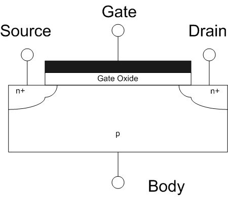
The field-effect transistor (FET) is a type of transistor that uses an electric field to control the flow of current in a semiconductor. FETs (JFETs or MOSFETs) are devices with three terminals: ''source'', ''gate'', and ''drain''. FETs control the flow of current by the application of a voltage to the gate, which in turn alters the conductivity between the drain and source. FETs are also known as unipolar transistors since they involve single-carrier-type operation. That is, FETs use either electrons (n-channel) or holes (p-channel) as charge carriers in their operation, but not both. Many different types of field effect transistors exist. Field effect transistors generally display very high input impedance at low frequencies. The most widely used field-effect transistor is the MOSFET (metal-oxide-semiconductor field-effect transistor). History The concept of a field-effect transistor (FET) was first patented by Austro-Hungarian physicist Julius Edgar Lilienfeld in 1925 an ... [...More Info...] [...Related Items...] OR: [Wikipedia] [Google] [Baidu] |
Circuit Diagram For RC-Phase Shift Oscillator Using JFET
Circuit may refer to: Science and technology Electrical engineering * Electrical circuit, a complete electrical network with a closed-loop giving a return path for current ** Analog circuit, uses continuous signal levels ** Balanced circuit, paths are impedance-matched ** Circuit analysis, the process of finding the voltages across, and the currents through, every component in an electrical circuit ** Circuit diagram, a graphical representation of an electrical circuit ** Digital circuit, uses discrete signal levels ** Electronic circuit, contains "active" (nonlinear) electronic components capable of performing amplification, computation, and data transfer *** Asynchronous circuit, or self-timed circuit, a sequential digital logic circuit that is not governed by a clock circuit or global clock signal *** Integrated circuit, a set of electronic circuits on a small "chip" of semiconductor material **** Mixed-signal integrated circuit, contains both analog and digital signa ... [...More Info...] [...Related Items...] OR: [Wikipedia] [Google] [Baidu] |


