|
Jackshaft
A jackshaft, also called a ''countershaft'', is a common mechanical design component used to transfer or synchronize rotational force in a machine. A jackshaft is often just a short stub with supporting bearings on the ends and two pulleys, gears, or cranks attached to it. In general, a jackshaft is any shaft that is used as an intermediary transmitting power from a driving shaft to a driven shaft. History Jackshaft The oldest uses of the term ''jackshaft'' appear to involve shafts that were intermediate between water wheels or stationary steam engines and the line shafts of 19th century mills. In these early sources from New England mills in 1872 and 1880, the term ''"jack shaft"'' always appears in quotes. Another 1872 author wrote "Gear wheels are used in England to transmit the power of the engine to what is usually called the jack shaft."Coleman Sellers, Transmission of MotionJournal of the Franklin Institute Vol. LXIV, No. 5 (Nov. 1872); pages 305-319, ''countershaft'' i ... [...More Info...] [...Related Items...] OR: [Wikipedia] [Google] [Baidu] |
Jackshaft (locomotive)
A jackshaft is an intermediate shaft used to transfer power from a powered shaft such as the output shaft of an engine or motor to driven shafts such as the drive axles of a locomotive. As applied to railroad locomotives in the 19th and 20th centuries, jackshafts were typically in line with the drive axles of locomotives and connected to them by side rods. In general, each drive axle on a locomotive is free to move about one inch (2.5 cm) vertically relative to the frame, with the locomotive weight carried on springs. This means that if the engine, motor or transmission is rigidly attached to the locomotive frame, it cannot be rigidly connected to the axle. This problem can be solved by mounting the jackshaft on unsprung bearings and using side-rods or (in some early examples) chain drives.General Construction, Baldwin Gasoline Industrial LocomotiveBaldwin Locomotive Works Record No. 74, 1913; pages 7-9. Jackshafts were first used in early steam locomotives, although the de ... [...More Info...] [...Related Items...] OR: [Wikipedia] [Google] [Baidu] |
Jackshaft Two Belt Pulleys
A jackshaft, also called a ''countershaft'', is a common mechanical design component used to transfer or synchronize rotational force in a machine. A jackshaft is often just a short stub with supporting bearings on the ends and two pulleys, gears, or cranks attached to it. In general, a jackshaft is any shaft that is used as an intermediary transmitting power from a driving shaft to a driven shaft. History Jackshaft The oldest uses of the term ''jackshaft'' appear to involve shafts that were intermediate between water wheels or stationary steam engines and the line shafts of 19th century mills. In these early sources from New England mills in 1872 and 1880, the term ''"jack shaft"'' always appears in quotes. Another 1872 author wrote "Gear wheels are used in England to transmit the power of the engine to what is usually called the jack shaft."Coleman Sellers, Transmission of MotionJournal of the Franklin Institute Vol. LXIV, No. 5 (Nov. 1872); pages 305-319, ''countershaft'' i ... [...More Info...] [...Related Items...] OR: [Wikipedia] [Google] [Baidu] |
Side Rod
A coupling rod or side rod connects the driving wheels of a locomotive. Steam locomotives in particular usually have them, but some diesel and electric locomotives, especially older ones and shunters, also have them. The coupling rods transfer the power of drive to all wheels. Development Locomotion No. 1 was the first locomotive to employ coupling rods rather than chains. In the 1930s reliable roller bearing coupling rods were developed. Allowance for vertical motion In general, all railroad vehicles have spring suspension; without springs, irregularities in the track could lift wheels off the rail and cause impact damage to both rails and vehicles. Driving wheels are typically mounted so that they have around 1 inch (2.5 cm) of vertical motion. When there are only 2 coupled axles, this range of motion places only slight stress on the crank pins. With more axles, however, provision must be made to allow each axle to move vertically independently of the others without be ... [...More Info...] [...Related Items...] OR: [Wikipedia] [Google] [Baidu] |
Stationary Steam Engine
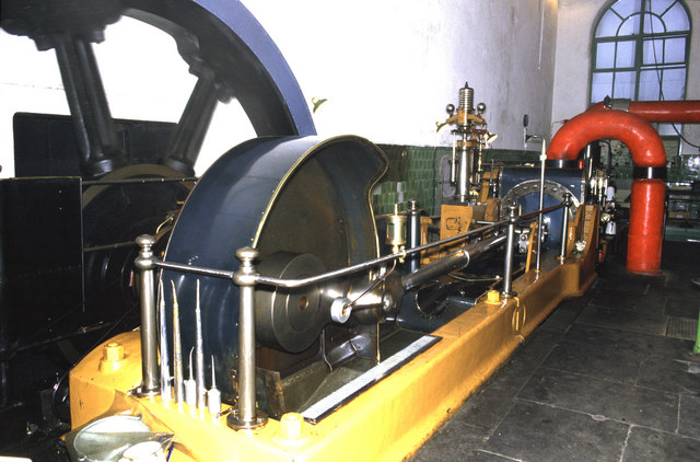
Stationary steam engines are fixed steam engines used for pumping or driving mills and factories, and for power generation. They are distinct from locomotive engines used on railways, traction engines for heavy steam haulage on roads, steam cars (and other motor vehicles), agricultural engines used for ploughing or threshing, marine engines, and the steam turbines used as the mechanism of power generation for most nuclear power plants. They were introduced during the 18th century and widely made for the whole of the 19th century and most of the first half of the 20th century, only declining as electricity supply and the internal combustion engine became more widespread. Types of stationary steam engine There are different patterns of stationary steam engines, distinguished by the layout of the cylinders and crankshaft: * Beam engines have a rocking beam providing the connection between the vertical cylinder and crankshaft. *Table engines have the crosshead above the vert ... [...More Info...] [...Related Items...] OR: [Wikipedia] [Google] [Baidu] |
Gristmill
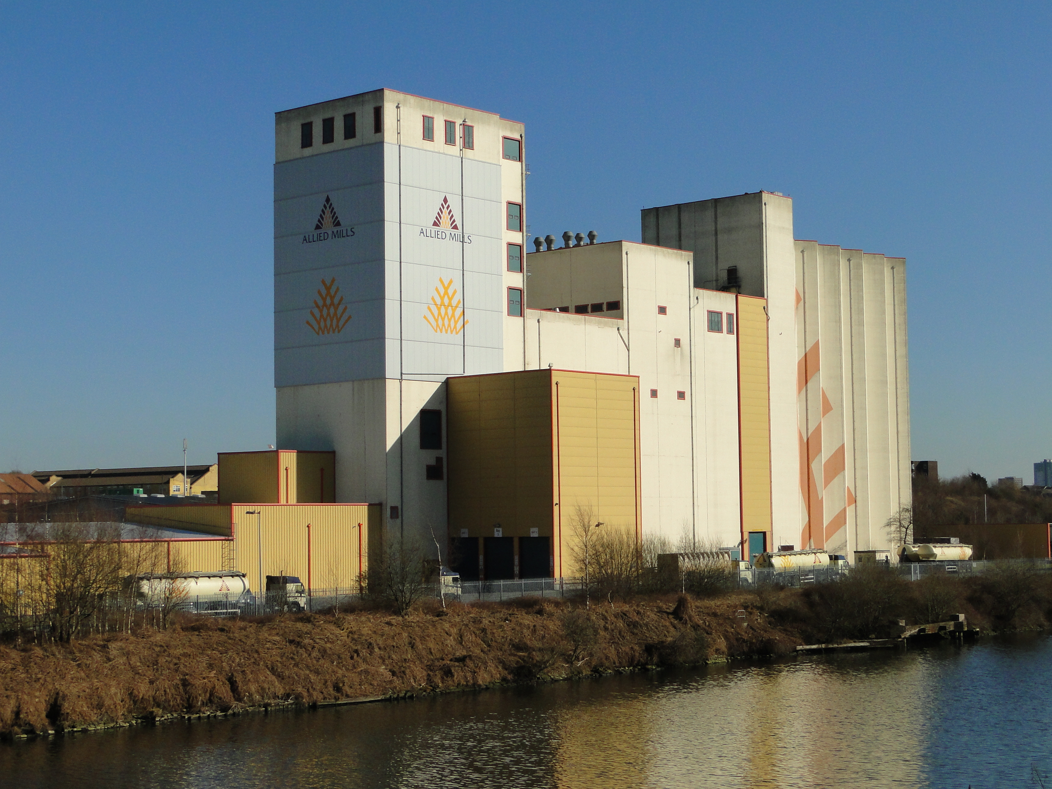
A gristmill (also: grist mill, corn mill, flour mill, feed mill or feedmill) grinds cereal grain into flour and Wheat middlings, middlings. The term can refer to either the Mill (grinding), grinding mechanism or the building that holds it. Grist is grain that has been separated from its chaff in preparation for grinding. History Early history The Greek geographer Strabo reports in his ''Geography'' a water-powered grain-mill to have existed near the palace of king Mithradates VI Eupator at Cabira, Asia Minor, before 71 BC. The early mills had horizontal paddle wheels, an arrangement which later became known as the "Water wheel#Vertical axis, Norse wheel", as many were found in Scandinavia. The paddle wheel was attached to a shaft which was, in turn, attached to the centre of the millstone called the "runner stone". The turning force produced by the water on the paddles was transferred directly to the runner stone, causing it to grind against a stationary "Mill machinery#Wat ... [...More Info...] [...Related Items...] OR: [Wikipedia] [Google] [Baidu] |
Industrial Revolution
The Industrial Revolution was the transition to new manufacturing processes in Great Britain, continental Europe, and the United States, that occurred during the period from around 1760 to about 1820–1840. This transition included going from hand production methods to machines, new chemical manufacturing and iron production processes, the increasing use of steam power and water power, the development of machine tools and the rise of the mechanized factory system. Output greatly increased, and a result was an unprecedented rise in population and in the rate of population growth. Textiles were the dominant industry of the Industrial Revolution in terms of employment, value of output and capital invested. The textile industry was also the first to use modern production methods. The Industrial Revolution began in Great Britain, and many of the technological and architectural innovations were of British origin. By the mid-18th century, Britain was the world's leadi ... [...More Info...] [...Related Items...] OR: [Wikipedia] [Google] [Baidu] |
Layshaft
A layshaft is an intermediate shaft within a gearbox that carries gears, but does not transfer the primary drive of the gearbox either in or out of the gearbox. Layshafts are best known through their use in car gearboxes, where they were a ubiquitous part of the rear-wheel drive layout. With the shift to front-wheel drive, the use of layshafts is now rarer. The ''driving shaft'' carries the input power into the gearbox. The ''driven shaft'' is the output shaft from the gearbox. In car gearboxes with layshafts, these two shafts emerge from opposite ends of the gearbox, which is convenient for RWD cars but may be a disadvantage for other layouts. For gearboxes in general, gear clusters mounted on a layshaft may either turn freely on a fixed shaft, or may be part of a shaft that then rotates in bearings. There may be multiple separate clusters on a shared shaft and these are allowed to turn freely relative to each other. Origins The term ''layshaft'' originates with watermill mac ... [...More Info...] [...Related Items...] OR: [Wikipedia] [Google] [Baidu] |
Drive Shaft
A drive shaft, driveshaft, driving shaft, tailshaft (Australian English), propeller shaft (prop shaft), or Cardan shaft (after Girolamo Cardano) is a component for transmitting mechanical power (physics), power and torque and rotation, usually used to connect other components of a drivetrain that cannot be connected directly because of distance or the need to allow for relative movement between them. As torque carriers, drive shafts are subject to torsion (mechanics), torsion and shear stress, equivalent to the difference between the input torque and the load. They must therefore be strong enough to bear the stress, while avoiding too much additional weight as that would in turn increase their inertia. To allow for variations in the alignment and distance between the driving and driven components, drive shafts frequently incorporate one or more universal joints, jaw couplings, or rag joints, and sometimes a Rotating spline, splined joint or prismatic joint. History The term ' ... [...More Info...] [...Related Items...] OR: [Wikipedia] [Google] [Baidu] |
Power Take-off
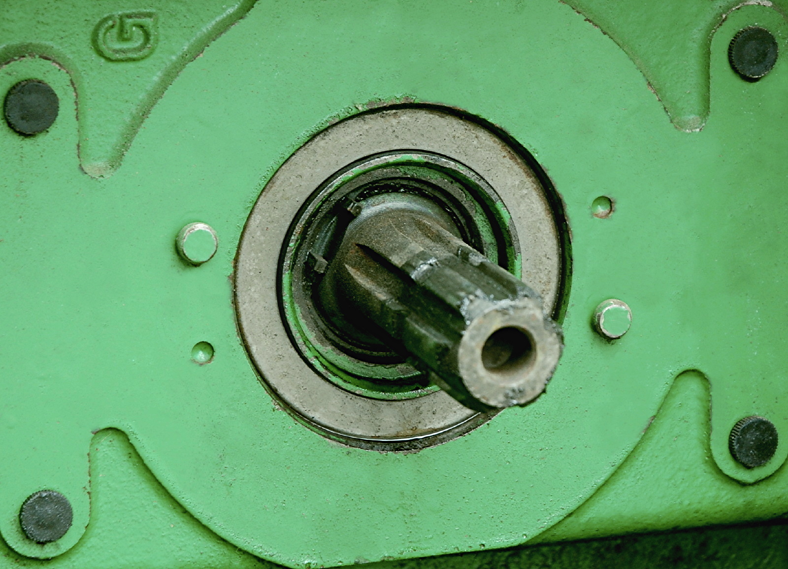
A power take-off or power takeoff (PTO) is one of several methods for taking power from a power source, such as a running engine, and transmitting it to an application such as an attached implement or separate machine. Most commonly, it is a splined drive shaft installed on a tractor or truck allowing implements with mating fittings to be powered directly by the engine. Semi-permanently mounted power take-offs can also be found on industrial and marine engines. These applications typically use a drive shaft and bolted joint to transmit power to a secondary implement or accessory. In the case of a marine application, such shafts may be used to power fire pumps. In aircraft applications, such an accessory drive may be used in conjunction with a constant speed drive. Jet aircraft have four types of PTO units: internal gearbox, external gearbox, radial drive shaft, and bleed air, which are used to power engine accessories. In some cases, aircraft power take-off systems also provid ... [...More Info...] [...Related Items...] OR: [Wikipedia] [Google] [Baidu] |
Pulley
A pulley is a wheel on an axle or shaft that is designed to support movement and change of direction of a taut cable or belt, or transfer of power between the shaft and cable or belt. In the case of a pulley supported by a frame or shell that does not transfer power to a shaft, but is used to guide the cable or exert a force, the supporting shell is called a block, and the pulley may be called a sheave. A pulley may have a groove or grooves between flanges around its circumference to locate the cable or belt. The drive element of a pulley system can be a rope, cable, belt, or chain. The earliest evidence of pulleys dates back to Ancient Egypt in the Twelfth Dynasty (1991-1802 BCE) and Mesopotamia in the early 2nd millennium BCE. In Roman Egypt, Hero of Alexandria (c. 10-70 CE) identified the pulley as one of six simple machines used to lift weights. Pulleys are assembled to form a block and tackle in order to provide mechanical advantage to apply large forces. Pulleys are ... [...More Info...] [...Related Items...] OR: [Wikipedia] [Google] [Baidu] |
Belt Drive
A belt is a loop of flexible material used to link two or more rotating shafts mechanically, most often parallel. Belts may be used as a source of motion, to transmit power efficiently or to track relative movement. Belts are looped over pulleys and may have a twist between the pulleys, and the shafts need not be parallel. In a two pulley system, the belt can either drive the pulleys normally in one direction (the same if on parallel shafts), or the belt may be crossed, so that the direction of the driven shaft is reversed (the opposite direction to the driver if on parallel shafts). The belt drive can also be used to change the speed of rotation, either up or down, by using different sized pulleys. As a source of motion, a conveyor belt is one application where the belt is adapted to carry a load continuously between two points. History The mechanical belt drive, using a pulley machine, was first mentioned in the text the ''Dictionary of Local Expressions'' by the Han Dyna ... [...More Info...] [...Related Items...] OR: [Wikipedia] [Google] [Baidu] |
.jpg)


.jpg)


