|
Interaction Overview Diagram
Interaction Overview Diagram is one of the fourteen types of diagrams of the Unified Modeling Language (UML), which can picture a control flow with nodes that can contain interaction diagrams. The interaction overview diagram is similar to the activity diagram, in that both visualize a sequence of activities. The difference is that, for an interaction overview, each individual activity is pictured as a frame which can contain a nested interaction diagram The Unified Modeling Language (UML) is a general-purpose, developmental modeling language in the field of software engineering that is intended to provide a standard way to visualize the design of a system. The creation of UML was originally m .... This makes the interaction overview diagram useful to "deconstruct a complex scenario that would otherwise require multiple if-then-else paths to be illustrated as a single sequence diagram". The other notation elements for interaction overview diagrams are the same as for activ ... [...More Info...] [...Related Items...] OR: [Wikipedia] [Google] [Baidu] |
Diagram
A diagram is a symbolic representation of information using visualization techniques. Diagrams have been used since prehistoric times on walls of caves, but became more prevalent during the Enlightenment. Sometimes, the technique uses a three-dimensional visualization which is then projected onto a two-dimensional surface. The word ''graph'' is sometimes used as a synonym for diagram. Overview The term "diagram" in its commonly used sense can have a general or specific meaning: * ''visual information device'' : Like the term " illustration", "diagram" is used as a collective term standing for the whole class of technical genres, including graphs, technical drawings and tables. * ''specific kind of visual display'' : This is the genre that shows qualitative data with shapes that are connected by lines, arrows, or other visual links. In science the term is used in both ways. For example, Anderson (1997) stated more generally: "diagrams are pictorial, yet abstract, represen ... [...More Info...] [...Related Items...] OR: [Wikipedia] [Google] [Baidu] |
Unified Modeling Language
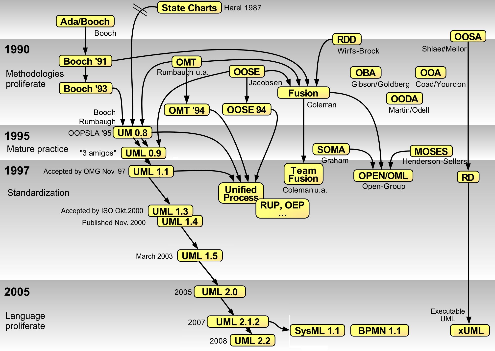
The Unified Modeling Language (UML) is a general-purpose, developmental modeling language in the field of software engineering that is intended to provide a standard way to visualize the design of a system. The creation of UML was originally motivated by the desire to standardize the disparate notational systems and approaches to software design. It was developed at Rational Software in 1994–1995, with further development led by them through 1996. In 1997, UML was adopted as a standard by the Object Management Group (OMG), and has been managed by this organization ever since. In 2005, UML was also published by the International Organization for Standardization (ISO) as an approved ISO standard. Since then the standard has been periodically revised to cover the latest revision of UML. In software engineering, most practitioners do not use UML, but instead produce informal hand drawn diagrams; these diagrams, however, often include elements from UML. History Before UML 1 ... [...More Info...] [...Related Items...] OR: [Wikipedia] [Google] [Baidu] |
Interaction Diagram
The Unified Modeling Language (UML) is a general-purpose, developmental modeling language in the field of software engineering that is intended to provide a standard way to visualize the design of a system. The creation of UML was originally motivated by the desire to standardize the disparate notational systems and approaches to software design. It was developed at Rational Software in 1994–1995, with further development led by them through 1996. In 1997, UML was adopted as a standard by the Object Management Group (OMG), and has been managed by this organization ever since. In 2005, UML was also published by the International Organization for Standardization (ISO) as an approved ISO standard. Since then the standard has been periodically revised to cover the latest revision of UML. In software engineering, most practitioners do not use UML, but instead produce informal hand drawn diagrams; these diagrams, however, often include elements from UML. History Before UML 1 ... [...More Info...] [...Related Items...] OR: [Wikipedia] [Google] [Baidu] |
Activity Diagram
Activity diagrams are graphical representations of workflows of stepwise activities and actions with support for choice, iteration and concurrency. In the Unified Modeling Language, activity diagrams are intended to model both computational and organizational processes (i.e., workflows), as well as the data flows intersecting with the related activities. Although activity diagrams primarily show the overall flow of control, they can also include elements showing the flow of data between activities through one or more data stores. Construction Activity diagrams are constructed from a limited number of shapes, connected with arrows. The most important shape types: * ''ellipses'' represent ''actions''; * ''diamonds'' represent ''decisions''; * ''bars'' represent the start (''split'') or end (''join'') of concurrent activities; * a ''black circle'' represents the start (''initial node'') of the workflow; * an ''encircled black circle'' represents the end (''final node''). Arrows run ... [...More Info...] [...Related Items...] OR: [Wikipedia] [Google] [Baidu] |
