|
Ejector Wells
An injector is a system of ducting and nozzles used to direct the flow of a high-pressure fluid in such a way that a lower pressure fluid is entrained in the jet and carried through a duct to a region of higher pressure. It is a fluid-dynamic pump with no moving parts except a valve to control inlet flow. A steam injector is a typical application of the principle used to deliver cold water to a boiler against its own pressure, using its own live or exhaust steam, replacing any mechanical pump. When first developed, its operation was intriguing because it seemed paradoxical, almost like perpetual motion, but it was later explained using thermodynamics. Other types of injector may use other pressurised motive fluids such as air. Depending on the application, an injector can also take the form of an ''eductor-jet pump'', a ''water eductor'' or an ''aspirator''. An ''ejector'' operates on similar principles to create a vacuum feed connection for braking systems etc. History The ... [...More Info...] [...Related Items...] OR: [Wikipedia] [Google] [Baidu] |
Boiler Feed Injector Diagram
A boiler is a closed vessel in which fluid (generally water) is heated. The fluid does not necessarily boil. The heated or vaporized fluid exits the boiler for use in various processes or heating applications, including water heating, central heating, boiler-based power generation, cooking, and sanitation. Heat sources In a fossil fuel power plant using a steam cycle for power generation, the primary heat source will be combustion of coal, oil, or natural gas. In some cases byproduct fuel such as the carbon monoxide rich offgasses of a coke battery can be burned to heat a boiler; biofuels such as bagasse, where economically available, can also be used. In a nuclear power plant, boilers called steam generators are heated by the heat produced by nuclear fission. Where a large volume of hot gas is available from some process, a heat recovery steam generator or recovery boiler can use the heat to produce steam, with little or no extra fuel consumed; such a configuration is common ... [...More Info...] [...Related Items...] OR: [Wikipedia] [Google] [Baidu] |
Velocity
Velocity is the directional speed of an object in motion as an indication of its rate of change in position as observed from a particular frame of reference and as measured by a particular standard of time (e.g. northbound). Velocity is a fundamental concept in kinematics, the branch of classical mechanics that describes the motion of bodies. Velocity is a physical vector quantity; both magnitude and direction are needed to define it. The scalar absolute value (magnitude) of velocity is called , being a coherent derived unit whose quantity is measured in the SI (metric system) as metres per second (m/s or m⋅s−1). For example, "5 metres per second" is a scalar, whereas "5 metres per second east" is a vector. If there is a change in speed, direction or both, then the object is said to be undergoing an ''acceleration''. Constant velocity vs acceleration To have a ''constant velocity'', an object must have a constant speed in a constant direction. Constant direction cons ... [...More Info...] [...Related Items...] OR: [Wikipedia] [Google] [Baidu] |
Stephenson's Rocket
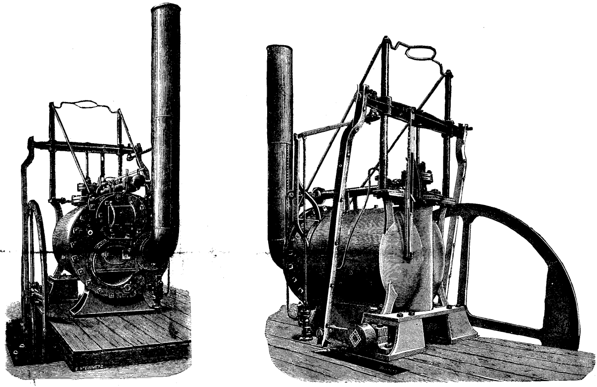
Stephenson's ''Rocket'' is an early steam locomotive of 0-2-2 wheel arrangement. It was built for and won the Rainhill Trials of the Liverpool and Manchester Railway (L&MR), held in October 1829 to show that improved locomotives would be more efficient than stationary steam engines. ''Rocket'' was designed and built by Robert Stephenson in 1829, and built at the Forth Street Works of his company in Newcastle upon Tyne. Though ''Rocket'' was by no means the first steam locomotive, it was the first to bring together several innovations to produce the most advanced locomotive of its day. It is the most famous example of an evolving design of locomotives by Stephenson that became the template for most steam engines in the following 150 years. The locomotive was preserved and displayed in the Science Museum in London until 2018, after which it was displayed at the National Railway Museum in York. Design Overall layout The locomotive had a tall smokestack chimney at the ... [...More Info...] [...Related Items...] OR: [Wikipedia] [Google] [Baidu] |
Richard Trevithick
Richard Trevithick (13 April 1771 – 22 April 1833) was a British inventor and mining engineer. The son of a mining captain, and born in the mining heartland of Cornwall, Trevithick was immersed in mining and engineering from an early age. He was an early pioneer of steam-powered road and rail transport, and his most significant contributions were the development of the first high-pressure steam engine and the first working railway steam locomotive. The world's first locomotive-hauled railway journey took place on 21 February 1804, when Trevithick's unnamed steam locomotive hauled a train along the tramway of the Penydarren Ironworks, in Merthyr Tydfil, Wales. Turning his interests abroad Trevithick also worked as a mining consultant in Peru and later explored parts of Costa Rica. Throughout his professional career he went through many ups and downs and at one point faced financial ruin, also suffering from the strong rivalry of many mining and steam engineers of the day. Durin ... [...More Info...] [...Related Items...] OR: [Wikipedia] [Google] [Baidu] |
Blastpipe
The blastpipe is part of the exhaust system of a steam locomotive that discharges exhaust steam from the cylinders into the smokebox beneath the chimney in order to increase the draught through the fire. History The primacy of discovery of the effect of directing the exhaust steam up the chimney as a means of providing draft through the fire is the matter of some controversy, Ahrons (1927) devoting significant attention to this matter. The exhaust from the cylinders on the first steam locomotive – built by Richard Trevithick – was directed up the chimney, and he noted its effect on increasing the draft through the fire at the time. At Wylam, Timothy Hackworth also employed a blastpipe on his earliest locomotives, but it is not clear whether this was an independent discovery or a copy of Trevithick's design. Shortly after Hackworth, George Stephenson also employed the same method, and again it is not clear whether that was an independent discovery or a copy of one of the other ... [...More Info...] [...Related Items...] OR: [Wikipedia] [Google] [Baidu] |
Smokebox Ejection Mechanism
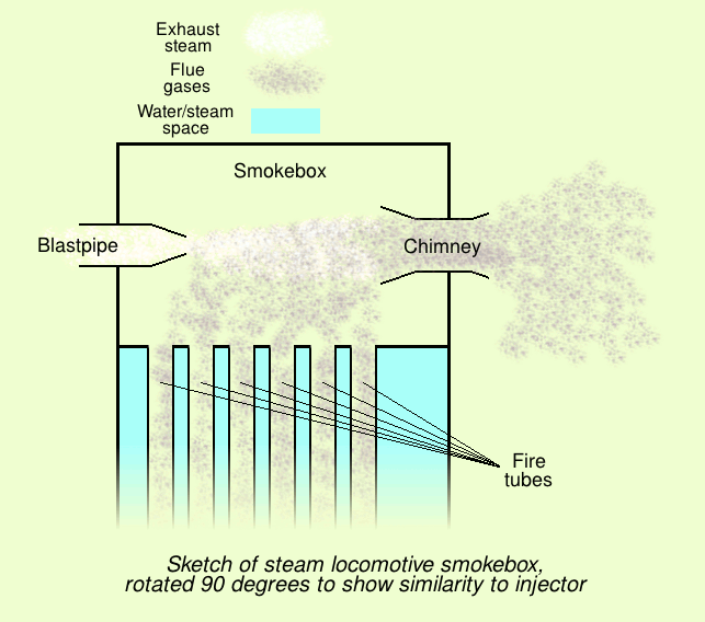
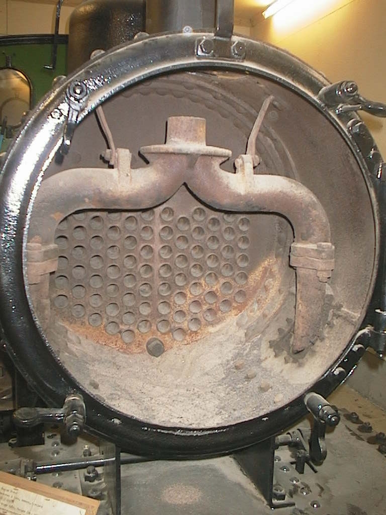
A smokebox is one of the major basic parts of a steam locomotive exhaust system. Smoke and hot gases pass from the firebox through tubes where they pass heat to the surrounding water in the boiler. The smoke then enters the smokebox, and is exhausted to the atmosphere through the chimney (or funnel). Early locomotives had no smokebox and relied on a long chimney to provide natural draught for the fire but smokeboxes were soon included in the design for two specific reasons. Firstly and most importantly, the blast of exhaust steam from the cylinders, when directed upwards through an airtight smokebox with an appropriate design of exhaust nozzle, effectively draws hot gases through the boiler tubes and flues and, consequently, fresh combustion air into the firebox. Secondly, the smokebox provides a convenient collection point for ash and cinders ("char") drawn through the boiler tubes, which can be easily cleaned out at the end of a working day. Without a smokebox, all char must p ... [...More Info...] [...Related Items...] OR: [Wikipedia] [Google] [Baidu] |
Crosshead
In mechanical engineering, a crosshead is a mechanical joint used as part of the slider-crank linkages of long reciprocating engines (either internal combustion or steam) and reciprocating compressors to eliminate sideways force on the piston. Also, the crosshead enables the connecting rod to freely move outside the cylinder. Because of the very small bore-to-stroke ratio on such engines, the connecting rod would hit the cylinder walls and block the engine from rotating if the piston was attached directly to the connecting rod like on trunk engines. Therefore, the longitudinal dimension of the crosshead must be matched to the stroke of the engine. Overview On smaller engines, the connecting rod links the piston and the crankshaft directly, but this transmits sideways forces to the piston, since the crankpin (and thus the direction the force is applied) moves from side to side with the rotary motion of the crank. These transverse forces are tolerable in a smaller engine. A large ... [...More Info...] [...Related Items...] OR: [Wikipedia] [Google] [Baidu] |
Regulation Of Railways Act 1889
The Regulation of Railways Act 1889 (52 & 53 Vict c 57) is an Act of the Parliament of the United Kingdom. It is one of the Railway Regulation Acts 1840 to 1893.The Short Titles Act 1896, section 2(1) and Schedule 2 It was enacted following the Armagh rail disaster. Safety It empowered the Board of Trade to require any railway company to: * adopt the block system of signalling on any passenger railway; * provide for the interlocking of points and signals on such railways; * provide for and use on all passenger trains continuous brakes; the brakes must be instantaneous in action; self applying in the event of any failure in continuity; capable of being applied to every vehicle of the train; and in regular use in daily working. Provision was made to enable the railway companies to issue debentures to pay for the capital cost of the equipment. There were also provisions regarding reporting the number of persons in safety-related employment who worked more than a specified number ... [...More Info...] [...Related Items...] OR: [Wikipedia] [Google] [Baidu] |
Railway Brake
A railway brake is a type of brake used on the cars of railway trains to enable deceleration, control acceleration (downhill) or to keep them immobile when parked. While the basic principle is similar to that on road vehicle usage, operational features are more complex because of the need to control multiple linked carriages and to be effective on vehicles left without a prime mover. Clasp brakes are one type of brakes historically used on trains. Early days In the earliest days of railways, braking technology was primitive. The first trains had brakes operative on the locomotive tender and on vehicles in the train, where "porters" or, in the United States brakemen, travelling for the purpose on those vehicles operated the brakes. Some railways fitted a special deep-noted brake whistle to locomotives to indicate to the porters the necessity to apply the brakes. All the brakes at this stage of development were applied by operation of a screw and linkage to brake blocks applied ... [...More Info...] [...Related Items...] OR: [Wikipedia] [Google] [Baidu] |
Ejector Or Injector
An injector is a system of ducting and nozzles used to direct the flow of a high-pressure fluid in such a way that a lower pressure fluid is entrained in the jet and carried through a duct to a region of higher pressure. It is a fluid-dynamic pump with no moving parts except a valve to control inlet flow. A steam injector is a typical application of the principle used to deliver cold water to a boiler against its own pressure, using its own live or exhaust steam, replacing any mechanical pump. When first developed, its operation was intriguing because it seemed paradoxical, almost like perpetual motion, but it was later explained using thermodynamics. Other types of injector may use other pressurised motive fluids such as air. Depending on the application, an injector can also take the form of an ''eductor-jet pump'', a ''water eductor'' or an ''aspirator''. An '' ejector'' operates on similar principles to create a vacuum feed connection for braking systems etc. History The ... [...More Info...] [...Related Items...] OR: [Wikipedia] [Google] [Baidu] |
1913 Ais Gill Rail Accident
The Ais Gill rail accident occurred on the Settle–Carlisle line in Northwest England on 2 September 1913. Two long trains were both ascending a steep gradient with some difficulty, because their engines generated barely enough power to carry the load. When the first train stopped to build-up steam pressure, the driver and fireman of the second train were distracted by maintenance routines, and failed to observe the warning signals. The collision wrecked several carriages, which were then engulfed by flammable gas, killing 16 people and injuring 38. Incident The two trains involved were both passenger trains, which had left Carlisle railway station in the early hours of 2 September, destined for St Pancras station. The Midland Railway, which owned and operated the Settle-Carlisle line, had a policy of using small engines, and the two locomotives had barely sufficient power to surmount the steep gradients on the line with the heavy trains they were assigned. In theory, the lo ... [...More Info...] [...Related Items...] OR: [Wikipedia] [Google] [Baidu] |
Check Valve
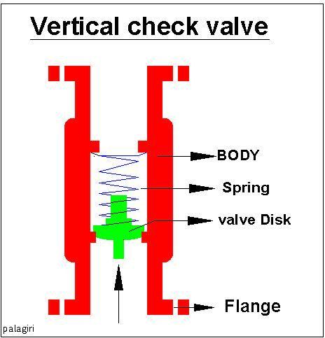
A check valve, non-return valve, reflux valve, retention valve, foot valve, or one-way valve is a valve that normally allows fluid (liquid or gas) to flow through it in only one direction. Check valves are two-port valves, meaning they have two openings in the body, one for fluid to enter and the other for fluid to leave. There are various types of check valves used in a wide variety of applications. Check valves are often part of common household items. Although they are available in a wide range of sizes and costs, check valves generally are very small, simple, and inexpensive. Check valves work automatically and most are not controlled by a person or any external control; accordingly, most do not have any valve handle or stem. The bodies (external shells) of most check valves are made of plastic or metal. An important concept in check valves is the cracking pressure which is the minimum differential upstream pressure between inlet and outlet at which the valve will operate. ... [...More Info...] [...Related Items...] OR: [Wikipedia] [Google] [Baidu] |


