|
Coupling
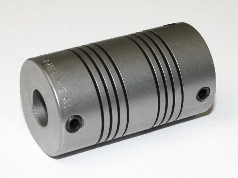
A coupling is a device used to connect two shafts together at their ends for the purpose of transmitting power. The primary purpose of couplings is to join two pieces of rotating equipment while permitting some degree of misalignment or end movement or both. In a more general context, a coupling can also be a mechanical device that serves to connect the ends of adjacent parts or objects. Couplings do not normally allow disconnection of shafts during operation, however there are torque-limiting couplings which can slip or disconnect when some torque limit is exceeded. Selection, installation and maintenance of couplings can lead to reduced maintenance time and maintenance cost. Uses Shaft couplings are used in machinery for several purposes. A primary function is to transfer power from one end to another end (ex: motor transfer power to pump through coupling). Other common uses: * To alter the vibration characteristics of rotating units * To connect the driving and the driven ... [...More Info...] [...Related Items...] OR: [Wikipedia] [Google] [Baidu] |
Universal Joint
A universal joint (also called a universal coupling or U-joint) is a joint or coupling connecting rigid shafts whose axes are inclined to each other. It is commonly used in shafts that transmit rotary motion. It consists of a pair of hinges located close together, oriented at 90° to each other, connected by a cross shaft. The universal joint is not a constant-velocity joint. U-joints are also sometimes called by various eponymous names, as follows: * Cardan joint, after Gerolamo Cardano, a polymath of the 16th century who contributed to knowledge of various clever mechanisms, including gimbals * Hooke joint or Hooke's joint, after Robert Hooke, a polymath of the 17th century who contributed to knowledge of various clever mechanisms * Spicer joint, after Clarence W. Spicer and the Spicer Manufacturing Company, who manufactured U joints * Hardy Spicer joint, after the Hardy Spicer brand, a successor to the Spicer brand History The main concept of the universal joi ... [...More Info...] [...Related Items...] OR: [Wikipedia] [Google] [Baidu] |
Constant-velocity Joint
Constant-velocity joints (also known as homokinetic or CV joints) are mechanical joints which allow a drive shaft to transmit power through a variable angle, at constant rotational speed, without an appreciable increase in friction or play. They are mainly used in front-wheel drive vehicles. Modern rear-wheel drive cars with independent rear suspension typically use CV joints at the ends of the rear axle halfshafts and increasingly use them on the drive shaft. History The universal joint, one of the earliest means of transmitting power between two angled shafts, was invented by Gerolamo Cardano in the 16th century. The fact that it failed to maintain constant velocity during rotation was recognized by Robert Hooke in the 17th century, who proposed the first constant velocity joint, consisting of two Cardan joints offset by 90 degrees, so as to cancel out the velocity variations. This is the "double Cardan". Many different types of constant-velocity joints have been inven ... [...More Info...] [...Related Items...] OR: [Wikipedia] [Google] [Baidu] |
Rotating Spline
Splines are ridges or teeth on a drive shaft that matches with grooves in a mating piece and transfer torque to it, maintaining the angular correspondence between them. For instance, a gear mounted on a shaft might use a male spline on the shaft that matches the female spline on the gear. The splines on the pictured drive shaft match with the female splines in the center of the clutch plate, while the smooth tip of the axle is supported in the pilot bearing in the flywheel. An alternative to splines is a keyway and key, though splines provide a longer fatigue life, and can carry significantly greater torques for the size. Types There are several types of splines: ;Parallel key spline: where the sides of the equally spaced grooves are parallel in both directions, radial and axial. ;Involute spline: where the sides of the equally spaced grooves are involute, as with an involute gear, but not as tall. The curves increase strength by decreasing stress concentrations. ;Crown ... [...More Info...] [...Related Items...] OR: [Wikipedia] [Google] [Baidu] |
Windsurfing
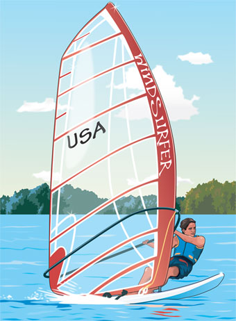
Windsurfing is a wind propelled water sport that is a combination of sailing and surfing. It is also referred to as "sailboarding" and "boardsailing", and emerged in the late 1960s from the aerospace and surf culture of California. Windsurfing gained a popular following across Europe and North America by the late 1970s and had achieved significant global popularity by the 1980s. Windsurfing became an olympic sport in 1984. Newer variants include windfoiling, kiteboarding and wingfoiling. Hydrofoil fins under the board allow the boards to safely lift out of the water and fly silently and smoothly above the surface even in lighter winds. Windsurfing is a recreational, family friendly sport, most popular at flat water locations around the world that offer safety and accessibility for beginner and intermediate participants. Technique and equipment have evolved over the years Major competitive disciplines include slalom, wave and freestyle. Increasingly, "foiling" is replacing t ... [...More Info...] [...Related Items...] OR: [Wikipedia] [Google] [Baidu] |
Vibration
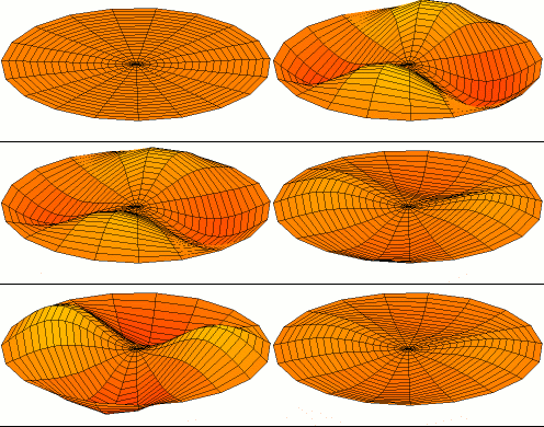
Vibration is a mechanical phenomenon whereby oscillations occur about an equilibrium point. The word comes from Latin ''vibrationem'' ("shaking, brandishing"). The oscillations may be periodic, such as the motion of a pendulum—or random, such as the movement of a tire on a gravel road. Vibration can be desirable: for example, the motion of a tuning fork, the reed in a woodwind instrument or harmonica, a mobile phone, or the cone of a loudspeaker. In many cases, however, vibration is undesirable, wasting energy and creating unwanted sound. For example, the vibrational motions of engines, electric motors, or any mechanical device in operation are typically unwanted. Such vibrations could be caused by imbalances in the rotating parts, uneven friction, or the meshing of gear teeth. Careful designs usually minimize unwanted vibrations. The studies of sound and vibration are closely related. Sound, or pressure waves, are generated by vibrating structures (e.g. vocal cords); ... [...More Info...] [...Related Items...] OR: [Wikipedia] [Google] [Baidu] |
Torque Density
Torque density is a measure of the torque-carrying capability of a mechanical component. It is the ratio of torque capability to volume and is expressed in units of torque per volume. Torque density is a system property since it depends on the design of each element of the component being examined and their interconnection. Torque density is useful during the concept evaluation stage of mechanical designs, especially in power train design problems. Typically, it will be one of many factors used to assign potential success measures to each concept. For example, in the upgrade of a drive train for a set of rolls in a rolling mill, space is often dictated by the configuration of current components. There may be several types of devices that can perform the function of an existing component that must be replaced. The relative torque densities of the devices may be an important determinant for which design is ultimately selected, although it will often compete with other factors su ... [...More Info...] [...Related Items...] OR: [Wikipedia] [Google] [Baidu] |
Gear
A gear is a rotating circular machine part having cut teeth or, in the case of a cogwheel or gearwheel, inserted teeth (called ''cogs''), which mesh with another (compatible) toothed part to transmit (convert) torque and speed. The basic principle behind the operation of gears is analogous to the basic principle of levers. A gear may also be known informally as a cog. Geared devices can change the speed, torque, and direction of a power source. Gears of different sizes produce a change in torque, creating a mechanical advantage, through their ''gear ratio'', and thus may be considered a simple machine. The rotational speeds, and the torques, of two meshing gears differ in proportion to their diameters. The teeth on the two meshing gears all have the same shape. Two or more meshing gears, working in a sequence, are called a gear train or a ''transmission''. The gears in a transmission are analogous to the wheels in a crossed, belt pulley system. An advantage of gears is t ... [...More Info...] [...Related Items...] OR: [Wikipedia] [Google] [Baidu] |
Cross Section (geometry)
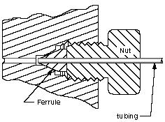
In geometry and science, a cross section is the non-empty intersection of a solid body in three-dimensional space with a plane, or the analog in higher- dimensional spaces. Cutting an object into slices creates many parallel cross-sections. The boundary of a cross-section in three-dimensional space that is parallel to two of the axes, that is, parallel to the plane determined by these axes, is sometimes referred to as a contour line; for example, if a plane cuts through mountains of a raised-relief map parallel to the ground, the result is a contour line in two-dimensional space showing points on the surface of the mountains of equal elevation. In technical drawing a cross-section, being a projection of an object onto a plane that intersects it, is a common tool used to depict the internal arrangement of a 3-dimensional object in two dimensions. It is traditionally crosshatched with the style of crosshatching often indicating the types of materials being used. Wit ... [...More Info...] [...Related Items...] OR: [Wikipedia] [Google] [Baidu] |
