|
Countersteam Brake
A countersteam brake is a brake on a steam locomotive that uses the engine (specifically the cylinders) to help brake the locomotive. It uses the working principle of steam cylinders fitted with slide or piston valves such that, by changing the configuration of the valve gear, the motion of the valves is also altered such that they work in opposition to the movement of the pistons. Because of the inertia of a steam locomotive in its initial direction of travel, changing the direction in which the steam cylinders have to work acts first to brake the movement of the connecting rod, which in turn slows the transmission of power to the drive of the locomotive until it stops. The countersteam brake is often confused with the counterpressure brake, which works with air, not steam, and acts as a dynamic brake. Unlike the countersteam brake, the counterpressure brake is permitted to be used as an independent braking system in its own right. Operation The countersteam brake is actuall ... [...More Info...] [...Related Items...] OR: [Wikipedia] [Google] [Baidu] |
Steam Locomotive
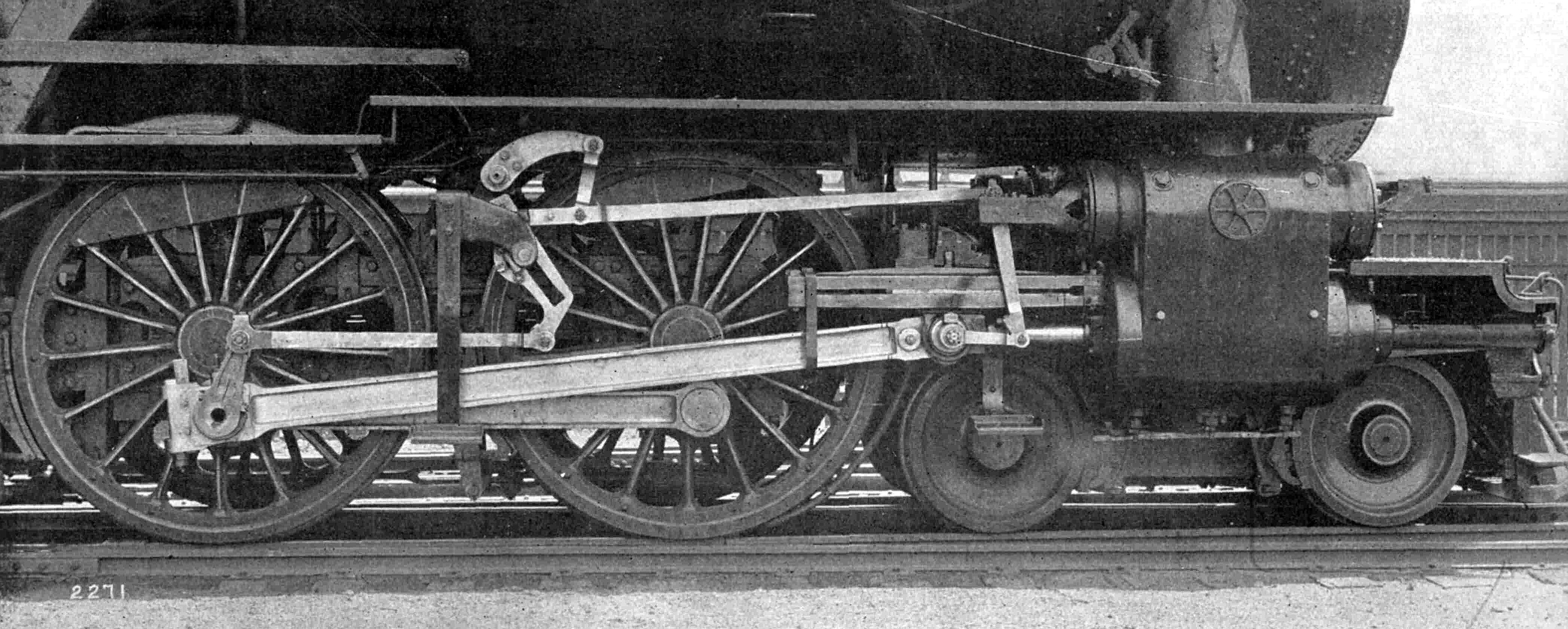
A steam locomotive is a locomotive that provides the force to move itself and other vehicles by means of the expansion of steam. It is fuelled by burning combustible material (usually coal, oil or, rarely, wood) to heat water in the locomotive's boiler to the point where it becomes gaseous and its volume increases 1,700 times. Functionally, it is a steam engine on wheels. In most locomotives, the steam is admitted alternately to each end of its cylinders, in which pistons are mechanically connected to the locomotive's main wheels. Fuel and water supplies are usually carried with the locomotive, either on the locomotive itself or in a tender coupled to it. Variations in this general design include electrically-powered boilers, turbines in place of pistons, and using steam generated externally. Steam locomotives were first developed in the United Kingdom during the early 19th century and used for railway transport until the middle of the 20th century. Richard Trevithick ... [...More Info...] [...Related Items...] OR: [Wikipedia] [Google] [Baidu] |
Cylinder (locomotive)
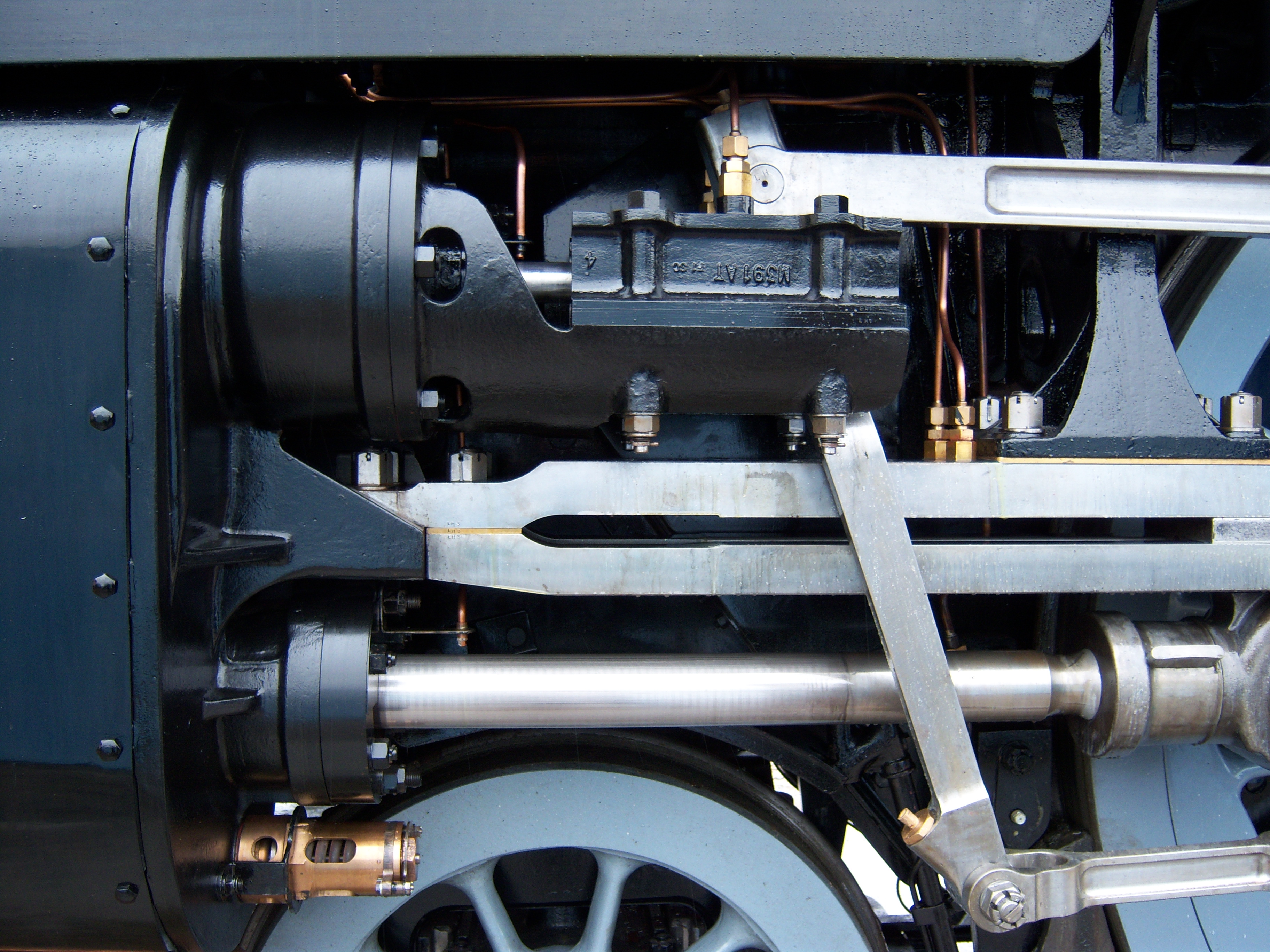
The cylinder is the power-producing element of the steam engine powering a steam locomotive. The cylinder is made pressure-tight with end covers and a piston; a valve distributes the steam to the ends of the cylinder. Cylinders were cast in iron and later made of steel. The cylinder casting includes other features such as (in the case of the early Rocket locomotive) valve ports and mounting feet. The last big American locomotives incorporated the cylinders as part of huge one-piece steel castings that were the main frame of the locomotive. Renewable wearing surfaces were needed inside the cylinders and provided by cast-iron bushings. The way the valve controlled the steam entering and leaving the cylinder was known as steam distribution and shown by the shape of the indicator diagram. What happened to the steam inside the cylinder was assessed separately from what happened in the boiler and how much friction the moving machinery had to cope with. This assessment was known as "e ... [...More Info...] [...Related Items...] OR: [Wikipedia] [Google] [Baidu] |
Slide Valve
The slide valve is a rectilinear valve used to control the admission of steam into and emission of exhaust from the cylinder of a steam engine. Use In the 19th century, most steam locomotives used slide valves to control the flow of steam into and out of the cylinders. In the 20th century, slide valves were gradually superseded by piston valves, particularly in engines using superheated steam. There were two reasons for this: * With piston valves, the steam passages can be made shorter. This reduces resistance to the flow of steam and improves efficiency. * It is difficult to lubricate slide valves adequately in the presence of superheated steam. Murdoch's D slide valve The D slide valve, or more specifically Long D slide valve, is a form of slide valve, invented by William Murdoch and patented in 1799. It is named after the hollow central D-sectioned piston. This valve worked by "connecting the upper and lower valves so as to be worked by one rod or spindle, and in maki ... [...More Info...] [...Related Items...] OR: [Wikipedia] [Google] [Baidu] |
Piston Valve (steam Engine)
Piston valves are one form of valve used to control the flow of steam within a steam engine or locomotive. They control the admission of steam into the cylinders and its subsequent exhausting, enabling a locomotive to move under its own power. The valve consists of two piston heads on a common spindle moving inside a steam chest, which is essentially a mini-cylinder located either above or below the main cylinders of the locomotive. Overview In the 19th century, steam locomotives used slide valves to control the flow of steam into and out of the cylinders. In the 20th century, slide valves were gradually superseded by piston valves, particularly in engines using superheated steam. There were two reasons for this: * It is difficult to lubricate slide valves adequately in the presence of superheated steam * With piston valves, the steam passages can be made shorter. This, particularly following the work of André Chapelon, reduces resistance to the flow of steam and improves eff ... [...More Info...] [...Related Items...] OR: [Wikipedia] [Google] [Baidu] |
Valve Gear
The valve gear of a steam engine is the mechanism that operates the inlet and exhaust valves to admit steam into the cylinder and allow exhaust steam to escape, respectively, at the correct points in the cycle. It can also serve as a reversing gear. It is sometimes referred to as the "motion". Purpose In the simple case, this can be a relatively simple task as in the internal combustion engine in which the valves always open and close at the same points. This is not the ideal arrangement for a steam engine, though, because greatest power is achieved by keeping the inlet valve open throughout the power stroke (thus having full boiler pressure, minus transmission losses, against the piston throughout the stroke) while peak efficiency is achieved by only having the inlet valve open for a short time and then letting the steam expand in the cylinder (expansive working). The point at which steam stops being admitted to the cylinder is known as the '' cutoff'', and the optimal positio ... [...More Info...] [...Related Items...] OR: [Wikipedia] [Google] [Baidu] |
Connecting Rod
A connecting rod, also called a 'con rod', is the part of a piston engine which connects the piston to the crankshaft. Together with the crank, the connecting rod converts the reciprocating motion of the piston into the rotation of the crankshaft. The connecting rod is required to transmit the compressive and tensile forces from the piston. In its most common form, in an internal combustion engine, it allows pivoting on the piston end and rotation on the shaft end. The predecessor to the connecting rod is a mechanic linkage used by water mills to convert rotating motion of the water wheel into reciprocating motion. The most common usage of connecting rods is in internal combustion engines or on steam engines. __TOC__ Origins The predecessor to the connecting length is the mechanical linkage used by Roman-era watermills. The earliest known example of this linkage has been found at the late 3rd century Hierapolis sawmill in Roman Asia (modern Turkey) and the 6th century ... [...More Info...] [...Related Items...] OR: [Wikipedia] [Google] [Baidu] |
Counterpressure Brake
The counter-pressure brake (German: ''Gegendruckbremse''), also named the Riggenbach counter-pressure brake after its inventor, Niklaus Riggenbach, is a dynamic railway brake on steam locomotives that brakes the locomotive using the driving cylinders. In doing so it reduces wear and tear and overheating of the driving wheel tyres and brake blocks and enables a continuously high brake force to be applied. The brake works by using the cylinders as air compressors and converting kinetic energy into heat. Steam is emitted during braking but this does not come from the boiler, it is produced by evaporation of water used to cool the cylinders. The main part of the system is piping and regulation of atmospheric air drawn into the cylinders, into which cooling water and oil is injected. Operation To use the cylinders as pumps necessitates complete reversal of the normal gas flow. Atmospheric air is drawn through the steam exhaust and compressed air ejected through the steam inlet. A separa ... [...More Info...] [...Related Items...] OR: [Wikipedia] [Google] [Baidu] |
Steam Engine
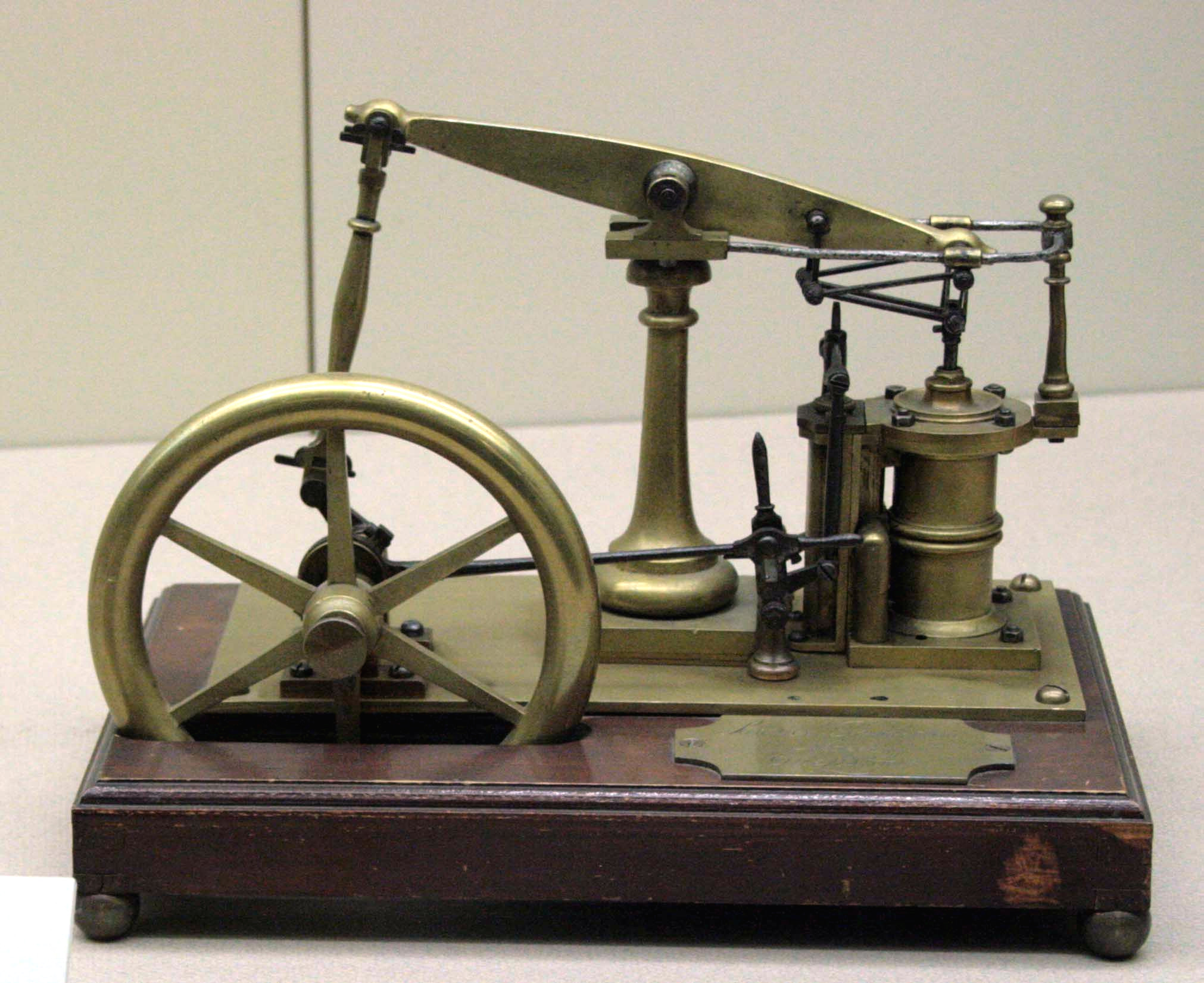
A steam engine is a heat engine that performs mechanical work using steam as its working fluid. The steam engine uses the force produced by steam pressure to push a piston back and forth inside a cylinder. This pushing force can be transformed, by a connecting rod and crank, into rotational force for work. The term "steam engine" is generally applied only to reciprocating engines as just described, not to the steam turbine. Steam engines are external combustion engines, where the working fluid is separated from the combustion products. The ideal thermodynamic cycle used to analyze this process is called the Rankine cycle. In general usage, the term ''steam engine'' can refer to either complete steam plants (including boilers etc.), such as railway steam locomotives and portable engines, or may refer to the piston or turbine machinery alone, as in the beam engine and stationary steam engine. Although steam-driven devices were known as early as the aeolipile in the f ... [...More Info...] [...Related Items...] OR: [Wikipedia] [Google] [Baidu] |
Compressed-air Brake
A railway air brake is a railway brake power braking system with compressed air as the operating medium. Modern trains rely upon a fail-safe air brake system that is based upon a design patented by George Westinghouse on April 13, 1869. The Westinghouse Air Brake Company was subsequently organized to manufacture and sell Westinghouse's invention. In various forms, it has been nearly universally adopted. The Westinghouse system uses air pressure to charge air reservoirs (tanks) on each car. Full air pressure causes each car to release the brakes. A subsequent reduction or loss of air pressure causes each car to apply its brakes, using the compressed air stored in its reservoirs. Overview Straight air brake In the air brake's simplest form, called the ''straight air system'', compressed air pushes on a piston in a cylinder. The piston is connected through mechanical linkage to brake shoes that can rub on the train wheels, using the resulting friction to slow the train. The ... [...More Info...] [...Related Items...] OR: [Wikipedia] [Google] [Baidu] |
Vacuum Brake
The vacuum brake is a braking system employed on trains and introduced in the mid-1860s. A variant, the automatic vacuum brake system, became almost universal in British train equipment and in countries influenced by British practice. Vacuum brakes also enjoyed a brief period of adoption in the United States, primarily on narrow-gauge railroads. Their limitations caused them to be progressively superseded by compressed air systems starting in the United Kingdom from the 1970s onward. The vacuum brake system is now obsolete; it is not in large-scale usage anywhere in the world, other than in South Africa, largely supplanted by air brakes. Introduction In the earliest days of railways, trains were slowed or stopped by the application of manually applied brakes on the locomotive and in brake vehicles through the train, and later by steam power brakes on locomotives. This was clearly unsatisfactory, given the slow and unreliable response times (each brake being separately applied by ... [...More Info...] [...Related Items...] OR: [Wikipedia] [Google] [Baidu] |
Steam Brake
A steam brake is a type of brake for steam locomotives and their tenders, whereby a steam cylinder works directly on the brake linkages. Steam brakes were primarily used on railways where vacuum brakes were used to brake the train, but where there was no vacuum brake on the steam locomotive itself, as for example in the United Kingdom, or where there was only a cable-operated brake (e.g. a Heberlein brake) running along the train, like for example in Saxony on the narrow gauge railways. Steam brakes are usually found today on heritage steam locomotives. Operation Steam is supplied to the steam brake cylinders from the locomotive boiler via a valve (the brake valve) which may have several fixed settings or be infinitely variable. The piston in the steam cylinder is set in motion by the steam admitted, the piston rod transfers the brake force via a system of rods to the brake blocks of the vehicle, thus achieving the braking effect. A return spring returns the piston to its r ... [...More Info...] [...Related Items...] OR: [Wikipedia] [Google] [Baidu] |
Railway Brakes
A railway brake is a type of brake used on the cars of railway trains to enable deceleration, control acceleration (downhill) or to keep them immobile when parked. While the basic principle is similar to that on road vehicle usage, operational features are more complex because of the need to control multiple linked carriages and to be effective on vehicles left without a prime mover. Clasp brakes are one type of brakes historically used on trains. Early days In the earliest days of railways, braking technology was primitive. The first trains had brakes operative on the locomotive tender and on vehicles in the train, where "porters" or, in the United States brakemen, travelling for the purpose on those vehicles operated the brakes. Some railways fitted a special deep-noted brake whistle to locomotives to indicate to the porters the necessity to apply the brakes. All the brakes at this stage of development were applied by operation of a screw and linkage to brake blocks applied ... [...More Info...] [...Related Items...] OR: [Wikipedia] [Google] [Baidu] |


.jpg)
.jpg)


_vacuum_brake_1.jpg)
