|
Computer-aided Manufacturing
Computer-aided manufacturing (CAM) also known as computer-aided modeling or computer-aided machining is the use of software to control machine tools in the manufacturing of work pieces. This is not the only definition for CAM, but it is the most common. It may also refer to the use of a computer to assist in all operations of a manufacturing plant, including planning, Industrial management, management, transportation and storage. Its primary purpose is to create a faster production process and components and tooling with more precise dimensions and material consistency, which in some cases, uses only the required amount of raw material (thus minimizing waste), while simultaneously reducing energy consumption. CAM is now a system used in schools and lower educational purposes. CAM is a subsequent computer-aided process after computer-aided design (CAD) and sometimes computer-aided engineering (CAE), as the model generated in CAD and verified in CAE can be input into CAM software, w ... [...More Info...] [...Related Items...] OR: [Wikipedia] [Google] [Baidu] |
CAD Model And CNC Machined Part
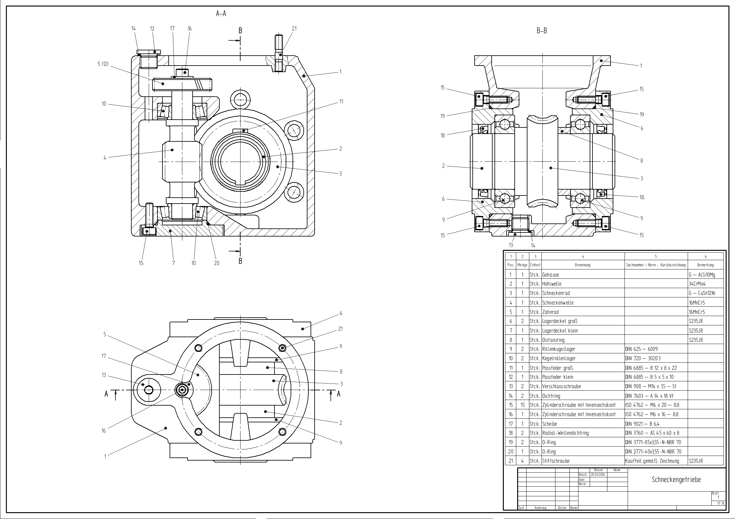
Computer-aided design (CAD) is the use of computers (or ) to aid in the creation, modification, analysis, or optimization of a design. This software is used to increase the productivity of the designer, improve the quality of design, improve communications through documentation, and to create a database for manufacturing. Designs made through CAD software help protect products and inventions when used in patent applications. CAD output is often in the form of electronic files for print, machining, or other manufacturing operations. The terms computer-aided drafting (CAD) and computer-aided design and drafting (CADD) are also used. Its use in designing electronic systems is known as ''electronic design automation'' (''EDA''). In mechanical design it is known as ''mechanical design automation'' (''MDA''), which includes the process of creating a technical drawing with the use of computer software. CAD software for mechanical design uses either Vector graphics, vector-based graph ... [...More Info...] [...Related Items...] OR: [Wikipedia] [Google] [Baidu] |
UNISURF
UNISURF was a pioneering surface CAD/ CAM system, designed to assist with car body design and tooling. It was developed by French engineer Pierre Bézier for Renault Renault S.A., commonly referred to as Groupe Renault ( , , , also known as the Renault Group in English), is a French Multinational corporation, multinational Automotive industry, automobile manufacturer established in 1899. The company curr ... in 1968, and entered full use at the company in 1975. One of the car parts developed with the assistance of UNISURF was the body of the Peugeot 204. By 1999, around 1,500 Renault employees made use of UNISURF for car design and manufacture. References External links * Computer-aided design software 1968 software Renault {{compu-graphics-stub ... [...More Info...] [...Related Items...] OR: [Wikipedia] [Google] [Baidu] |
Feature Recognition
The term "feature" implies different meanings in different engineering disciplines. This has resulted in many ambiguous definitions for feature. A feature, in computer-aided design (CAD), usually refers to a region of a part with some interesting geometric or topological properties.Pratt M.J. and Wilson P.R., 1985, Requirements for support of form features in a solid modeling system, ''CAM-I'', R-85-ASPP-01 These are more precisely called form features. Form features contain both shape information and parametric information of a region of interest. They are now ubiquitous in most current CAD software, where they are used as the primary means of creating 3D geometric models. Examples of form features are extruded boss, loft, etc. Form feature is not the only type of feature that is discussed in CAD literature. Sometimes a part's functional or manufacturing features of the subject of attention.Regli W.C., 1995, Geometric algorithms for recognition of features from solid models, PhD d ... [...More Info...] [...Related Items...] OR: [Wikipedia] [Google] [Baidu] |
Programmer
A programmer, computer programmer or coder is an author of computer source code someone with skill in computer programming. The professional titles Software development, ''software developer'' and Software engineering, ''software engineer'' are used for jobs that require a programmer. Identification Sometimes a programmer or job position is identified by the language used or target platform. For example, assembly language, assembly programmer, web developer. Job title The job titles that include programming tasks have differing connotations across the computer industry and to different individuals. The following are notable descriptions. A ''software developer'' primarily implements software based on specifications and fixes Software bug, bugs. Other duties may include code review, reviewing code changes and software testing, testing. To achieve the required skills for the job, they might obtain a computer science or associate degree, associate degree, attend a Cod ... [...More Info...] [...Related Items...] OR: [Wikipedia] [Google] [Baidu] |
Mass Production
Mass production, also known as mass production, series production, series manufacture, or continuous production, is the production of substantial amounts of standardized products in a constant flow, including and especially on assembly lines. Together with job production and batch production, it is one of the three main production methods. The term ''mass production'' was popularized by a 1926 article in the ''Encyclopædia Britannica'' supplement that was written based on correspondence with Ford Motor Company. ''The New York Times'' used the term in the title of an article that appeared before the publication of the ''Britannica'' article. The idea of mass production is applied to many kinds of products: from fluids and particulates handled in bulk (food, fuel, chemicals and mined minerals), to clothing, textiles, parts and assemblies of parts ( household appliances and automobiles). Some mass production techniques, such as standardized sizes and production lines, ... [...More Info...] [...Related Items...] OR: [Wikipedia] [Google] [Baidu] |
Direct Numerical Control
Direct numerical control (DNC), also known as distributed numerical control (also DNC), is a common manufacturing term for networking CNC machine tools. On some CNC machine controllers, the available memory is too small to contain the machining program (for example machining complex surfaces), so in this case the program is stored in a separate computer and sent ''directly'' to the machine, one block at a time. If the computer is connected to a number of machines it can ''distribute'' programs to different machines as required. Usually, the manufacturer of the control provides suitable DNC software. However, if this provision is not possible, some software companies provide DNC applications that fulfill the purpose. DNC networking or DNC communication is always required when CAM programs are to run on some CNC machine control. Wireless DNC is also used in place of hard-wired versions. Controls of this type are very widely used in industries with significant sheet metal fabricatio ... [...More Info...] [...Related Items...] OR: [Wikipedia] [Google] [Baidu] |
Parasolid
Parasolid is a geometric modeling kernel originally developed by Shape Data Limited, now owned and developed by Siemens Digital Industries Software. It can be licensed by other companies for use in their 3D computer graphics software products. Parasolid's abilities include model creation and editing utilities such as Boolean modeling operators, feature modeling support, advanced surfacing, thickening and hollowing, blending and filleting, and sheet modeling. It also incorporates modeling with mesh surfaces and lattices. Parasolid also includes tools for direct model editing, including tapering, offsetting, geometry replacement and removing feature details with automated regeneration of surrounding data. Parasolid also provides wide-ranging graphical and rendering support, including hidden-line, wireframe and drafting, tessellation, and model data inquiries. Parasolid XT format Parasolid parts are normally saved in XT format, which usually has the file extension .X_T. The ... [...More Info...] [...Related Items...] OR: [Wikipedia] [Google] [Baidu] |
STL (file Format)
STL is a file format native to the stereolithography CAD software created by 3D Systems. Chuck Hull, the inventor of stereolithography and 3D Systems’ founder, reports that the file extension is an abbreviation for ''stereolithography'', although it is also referred to as ''standard triangle language'' or ''standard tessellation language''. An STL file describes a raw, unstructured triangulated surface by the unit normal and vertices (ordered by the right-hand rule) of the triangles using a three-dimensional Cartesian coordinate system. In the original specification, all STL coordinates were required to be positive numbers, but this restriction is no longer enforced and negative coordinates are commonly encountered in STL files today. STL files contain no scale information, and the units are arbitrary. STL files describe only the surface geometry of a three-dimensional object without any representation of color, texture or other common CAD model attributes. The STL format ... [...More Info...] [...Related Items...] OR: [Wikipedia] [Google] [Baidu] |
IGES
The Initial Graphics Exchange Specification (IGES) is a vendor-neutral List of file formats, file format that allows the CAD data exchange, digital exchange of information among computer-aided design (CAD) systems. It is an ASCII-based textual format. The official title of IGES is ''Digital Representation for Communication of Product Definition Data'', first published in March, 1980 by the U.S. National Bureau of Standards as NBSIR 80-1978. Many documents (like early versions of the Defense Standards MIL-PRF-28000 and MIL-STD-1840) referred to it as American Society of Mechanical Engineers, ASME Y14.26M, the designation of the ANSI committee that approved IGES Version 1.0. Using IGES, a CAD user can exchange product data models in the form of circuit diagrams, wire frame model, wireframe, freeform surface modelling, freeform surface, Boundary representation, boundary (B-rep) or solid modeling (CSG) Representation (arts), representations. Applications supported by IGES include tra ... [...More Info...] [...Related Items...] OR: [Wikipedia] [Google] [Baidu] |
CAD Data Exchange
CAD data exchange is a method of Engineering drawing, drawing data exchange used to translate between different computer-aided design (Computer-aided design, CAD) authoring systems or between CAD and other downstream CAx systems. Many companies use different CAD systems and exchange CAD data file format with suppliers, customers, and subcontractors. Such formats are often proprietary. Transfer of data is necessary so that, for example, one organization can be developing a CAD model, while another performs analysis work on the same model; at the same time a third organization is responsible for manufacturing the product.Xu, X. (2009). ''Integrating advanced computer-aided design, manufacturing, and numerical control: Principles and implementations''. Hershey, PA: Information Science Reference. Since the 1980s, a Computer-aided technologies, range of different CAD technologies have emerged. They differ in their application aims, user interfaces, performance levels, and in data s ... [...More Info...] [...Related Items...] OR: [Wikipedia] [Google] [Baidu] |
Product Lifecycle Management
In industry, product lifecycle management (PLM) is the process of managing the entire lifecycle of a product from its inception through the engineering, design, and manufacture, as well as the service and disposal of manufactured products. PLM integrates people, data, processes, and business systems and provides a product information backbone for companies and their extended enterprises. History The inspiration for the burgeoning business process now known as PLM came from American Motors Corporation (AMC). The automaker was looking for a way to speed up its product development process to compete better against its larger competitors in 1985, according to François Castaing, Vice President for Product Engineering and Development. AMC focused its R&D efforts on extending the product lifecycle of its flagship products, particularly Jeeps, because it lacked the "massive budgets of General Motors, Ford, and foreign competitors." After introducing its compact Jeep Cherokee (X ... [...More Info...] [...Related Items...] OR: [Wikipedia] [Google] [Baidu] |
TRW Inc
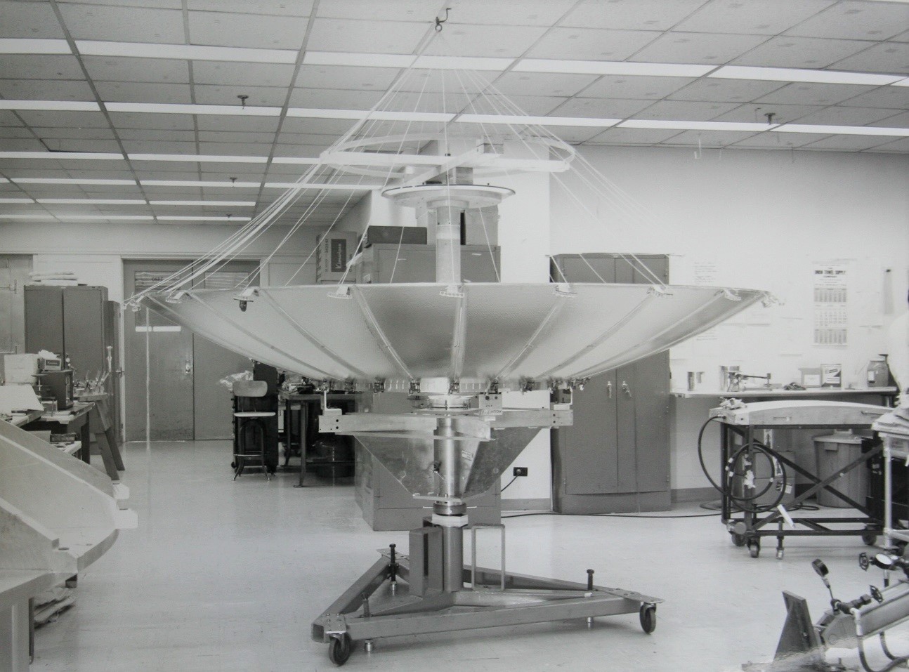
TRW Inc. was an American corporation involved in a variety of businesses, mainly aerospace, electronics, automotive, and credit reporting.http://www.fundinguniverse.com/company-histories/TRW-Inc-Company-History.html TRW Inc. It was a pioneer in multiple fields including electronic components, integrated circuits, computers, software and systems engineering. TRW built many spacecraft, including Pioneer 1, Pioneer 10, and several space-based observatories. It was #57 on the 1986 Fortune 500 list, and had 122,258 employees. The company was called Thompson Ramo Wooldridge Inc., after the 1958 merger of the Ramo-Wooldridge Corporation and Thompson Products. This was later shortened to TRW. The company was founded in 1901 and lasted for just over a century until being acquired by Northrop Grumman in 2002. It spawned a variety of corporations, including Pacific Semiconductors, The Aerospace Corporation, Bunker-Ramo and Experian. Its automotive businesses were sold off by Northro ... [...More Info...] [...Related Items...] OR: [Wikipedia] [Google] [Baidu] |


