|
Wilson Current Mirror
A Wilson current mirror is a three-terminal circuit (Fig. 1) that accepts an input current at the input terminal and provides a "mirrored" current source or sink output at the output terminal. The mirrored current is a precise copy of the input current. It may be used as a Wilson current source by applying a constant bias current to the input branch as in Fig. 2. The circuit is named after George R. Wilson, an integrated circuit design engineer who worked for Tektronix. Sedra, A.S. & Smith, K.C.: "Microelectronic Circuits, 6th Ed.", OUP (2010), pp. 539 - 541. Wilson devised this configuration in 1967 when he and Barrie Gilbert challenged each other to find an improved current mirror overnight that would use only three transistors. Wilson won the challenge.Gilbert, B., "Bipolar Current Mirrors," in "Analogue IC Design: the Current-Mode Approach," Eds. Toumazou, C., Lidgey, F. J. & Haigh, D. G., Peter Peregrinus Ltd. (1990), , pp. 268-275. Circuit operation There are three princ ... [...More Info...] [...Related Items...] OR: [Wikipedia] [Google] [Baidu] |
Current Mirror
A current mirror is a circuit designed to copy a current through one active device by controlling the current in another active device of a circuit, keeping the output current constant regardless of loading. The current being "copied" can be, and sometimes is, a varying signal current. Conceptually, an ideal current mirror is simply an ideal ''inverting current amplifier'' that reverses the current direction as well. Or it can consist of a current-controlled current source (CCCS). The current mirror is used to provide bias currents and active loads to circuits. It can also be used to model a more realistic current source (since ideal current sources don't exist). The circuit topology covered here is one that appears in many monolithic ICs. It is a Widlar mirror without an emitter degeneration resistor in the follower (output) transistor. This topology can only be done in an IC, as the matching has to be extremely close and cannot be achieved with discretes. Another topology i ... [...More Info...] [...Related Items...] OR: [Wikipedia] [Google] [Baidu] |
Circuit Idea/How The Wilson Current Mirror Keeps The Current
Circuit may refer to: Science and technology Electrical engineering * Electrical circuit, a complete electrical network with a closed-loop giving a return path for current ** Analog circuit, uses continuous signal levels ** Balanced circuit, paths are impedance-matched ** Circuit analysis, the process of finding the voltages across, and the currents through, every component in an electrical circuit ** Circuit diagram, a graphical representation of an electrical circuit ** Digital circuit, uses discrete signal levels ** Electronic circuit, contains "active" (nonlinear) electronic components capable of performing amplification, computation, and data transfer *** Asynchronous circuit, or self-timed circuit, a sequential digital logic circuit that is not governed by a clock circuit or global clock signal *** Integrated circuit, a set of electronic circuits on a small "chip" of semiconductor material **** Mixed-signal integrated circuit, contains both analog and digital signals ... [...More Info...] [...Related Items...] OR: [Wikipedia] [Google] [Baidu] |
Circuit Idea/How The Wilson Current Mirror Equalizes The Currents
Circuit may refer to: Science and technology Electrical engineering * Electrical circuit, a complete electrical network with a closed-loop giving a return path for current ** Analog circuit, uses continuous signal levels ** Balanced circuit, paths are impedance-matched ** Circuit analysis, the process of finding the voltages across, and the currents through, every component in an electrical circuit ** Circuit diagram, a graphical representation of an electrical circuit ** Digital circuit, uses discrete signal levels ** Electronic circuit, contains "active" (nonlinear) electronic components capable of performing amplification, computation, and data transfer *** Asynchronous circuit, or self-timed circuit, a sequential digital logic circuit that is not governed by a clock circuit or global clock signal *** Integrated circuit, a set of electronic circuits on a small "chip" of semiconductor material **** Mixed-signal integrated circuit, contains both analog and digital signals ... [...More Info...] [...Related Items...] OR: [Wikipedia] [Google] [Baidu] |
Widlar Current Source
] A Widlar current source is a modification of the basic two- transistor current mirror that incorporates an emitter degeneration resistor for only the output transistor, enabling the current source to generate low currents using only moderate resistor values. The Widlar circuit may be used with bipolar transistors, MOS transistors, and even vacuum tubes. An example application is the 741 operational amplifier, and Widlar used the circuit as a part in many designs.See, for example, Figure 2 i''IC voltage regulators'' This circuit is named after its inventor, Bob Widlar, and was patented in 1967.RJ Widlar: US Patent Number 03320439; Filed May 26, 1965; Granted May 16, 1967:Low-value current source for integrated circuits''/ref>See Widlar''Some circuit design techniques for linear integrated circuits''an''Design techniques for monolithic operational amplifiers''/ref> DC analysis Figure 1 is an example Widlar current source using bipolar transistors, where the emitter resisto ... [...More Info...] [...Related Items...] OR: [Wikipedia] [Google] [Baidu] |
University Of Manchester Institute Of Science And Technology
The University of Manchester Institute of Science and Technology (UMIST) was a university based in the centre of the city of Manchester in England. It specialised in technical and scientific subjects and was a major centre for research. On 1 October 2004, it amalgamated with the Victoria University of Manchester (commonly called the University of Manchester) to produce a new entity called the University of Manchester. UMIST gained its royal charter in 1956 and became a fully autonomous university in 1994. Previously its degrees were awarded by the Victoria University of Manchester. The UMIST motto was ''Scientia et Labore'' (By Knowledge and Work). Manchester Mechanics' Institute (1824–1882) The foundation of UMIST can be traced to 1824 during the Industrial Revolution when a group of Manchester businessmen and industrialists met in a public house, the Bridgewater Arms, to establish the ''Mechanics' Institute in Manchester'', where artisans could learn basic science, particu ... [...More Info...] [...Related Items...] OR: [Wikipedia] [Google] [Baidu] |
Cascode
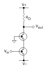
The cascode is a two-stage amplifier that consists of a common-emitter stage feeding into a common-base stage. Compared to a single amplifier stage, this combination may have one or more of the following characteristics: higher input–output isolation, higher input impedance, high output impedance, higher bandwidth. In modern circuits, the cascode is often constructed from two transistors ( BJTs or FETs), with one operating as a common emitter or common source and the other as a common base or common gate. The cascode improves input–output isolation (reduces reverse transmission), as there is no direct coupling from the output to input. This eliminates the Miller effect and thus contributes to a much higher bandwidth. History The use of a cascode (sometimes verbified to ''cascoding'') is a common technique for improving analog circuit performance, applicable to both vacuum tubes and transistors. The name "cascode" was coined in an article written by Frederick Vinton ... [...More Info...] [...Related Items...] OR: [Wikipedia] [Google] [Baidu] |
Miller Effect
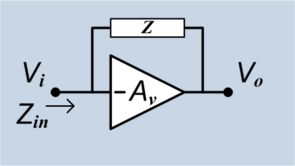
In electronics, the Miller effect accounts for the increase in the equivalent input capacitance of an inverting voltage amplifier due to amplification of the effect of capacitance between the input and output terminals. The virtually increased input capacitance due to the Miller effect is given by :C_=C (1+A_v)\, where -A_v is the voltage gain of the inverting amplifier (A_v positive) and C is the feedback capacitance. Although the term ''Miller effect'' normally refers to capacitance, any impedance connected between the input and another node exhibiting gain can modify the amplifier input impedance via this effect. These properties of the Miller effect are generalized in the Miller theorem. The Miller capacitance due to parasitic capacitance between the output and input of active devices like transistors and vacuum tubes is a major factor limiting their gain at high frequencies. Miller capacitance was identified in 1920 in triode vacuum tubes by John Milton Miller. History ... [...More Info...] [...Related Items...] OR: [Wikipedia] [Google] [Baidu] |
Harmonic Mean
In mathematics, the harmonic mean is one of several kinds of average, and in particular, one of the Pythagorean means. It is sometimes appropriate for situations when the average rate is desired. The harmonic mean can be expressed as the reciprocal of the arithmetic mean of the reciprocals of the given set of observations. As a simple example, the harmonic mean of 1, 4, and 4 is : \left(\frac\right)^ = \frac = \frac = 2\,. Definition The harmonic mean ''H'' of the positive real numbers x_1, x_2, \ldots, x_n is defined to be :H = \frac = \frac = \left(\frac\right)^. The third formula in the above equation expresses the harmonic mean as the reciprocal of the arithmetic mean of the reciprocals. From the following formula: :H = \frac. it is more apparent that the harmonic mean is related to the arithmetic and geometric means. It is the reciprocal dual of the arithmetic mean for positive inputs: :1/H(1/x_1 \ldots 1/x_n) = A(x_1 \ldots x_n) The harmonic mean is a Schur-conca ... [...More Info...] [...Related Items...] OR: [Wikipedia] [Google] [Baidu] |
Current Source
A current source is an electronic circuit that delivers or absorbs an electric current which is independent of the voltage across it. A current source is the dual of a voltage source. The term ''current sink'' is sometimes used for sources fed from a negative voltage supply. Figure 1 shows the schematic symbol for an ideal current source driving a resistive load. There are two types. An ''independent current source'' (or sink) delivers a constant current. A ''dependent current source'' delivers a current which is proportional to some other voltage or current in the circuit. Background , - align="center" , style="padding: 1em 2em 0;", , style="padding: 1em 2em 0;", , - align="center" , Voltage source , Current source , - align="center" , style="padding: 1em 2em 0;", , style="padding: 1em 2em 0;", , - align="center" , Controlled voltage source , Controlled current source , - align="center" , style="padding: 1em 2em 0;", , style="padding: 1em 2em 0;", , - align= ... [...More Info...] [...Related Items...] OR: [Wikipedia] [Google] [Baidu] |


