|
VORTAC
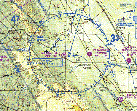
Very high frequency omnirange station (VOR) is a type of short-range radio navigation system for aircraft, enabling aircraft with a receiving unit to determine its position and stay on course by receiving radio signals transmitted by a network of fixed ground radio beacons. It uses frequencies in the very high frequency (VHF) band from 108.00 to 117.95 MHz. Developed in the United States beginning in 1937 and deployed by 1946, VOR became the standard air navigational system in the world,VOR VHF omnidirectional Range , Aviation Tutorial – Radio Navaids, kispo.net used by both commercial and general aviation, until supplanted by satellite navigation systems such as GPS in the early 21st century. As such ... [...More Info...] [...Related Items...] OR: [Wikipedia] [Google] [Baidu] |
Tactical Air Navigation System
A tactical air navigation system, commonly referred to by the acronym TACAN, is a navigation system used by military aircraft. It provides the user with bearing and distance (slant-range or hypotenuse) to a ground or ship-borne station. It is a more accurate version of the VOR/ DME system that provides bearing and range information for civil aviation. The DME portion of the TACAN system is available for civil use; at VORTAC facilities where a VOR is combined with a TACAN, civil aircraft can receive VOR/DME readings. Aircraft equipped with TACAN avionics can use this system for en route navigation as well as non-precision approaches to landing fields. The Space Shuttle is one such vehicle that was designed to use TACAN navigation but later upgraded with GPS as a replacement. The typical TACAN onboard user panel has control switches for setting the channel (corresponding to the desired surface station's assigned frequency), the operation mode for either transmit/receive (T/R, ... [...More Info...] [...Related Items...] OR: [Wikipedia] [Google] [Baidu] |
Radio Direction Finding
Direction finding (DF), or radio direction finding (RDF), isin accordance with International Telecommunication Union (ITU)defined as radio location that uses the reception of radio waves to determine the direction in which a radio station or an object is located. This can refer to radio or other forms of wireless communication, including radar signals detection and monitoring (ELINT/ESM). By combining the direction information from two or more suitably spaced receivers (or a single mobile receiver), the source of a transmission may be located via triangulation. Radio direction finding is used in the navigation of ships and aircraft, to locate emergency transmitters for search and rescue, for tracking wildlife, and to locate illegal or interfering transmitters. RDF was important in combating German threats during both the World War II Battle of Britain and the long running Battle of the Atlantic. In the former, the Air Ministry also used RDF to locate its own fighter grou ... [...More Info...] [...Related Items...] OR: [Wikipedia] [Google] [Baidu] |
Radio Navigation
Radio navigation or radionavigation is the application of radio frequencies to determine a position of an object on the Earth, either the vessel or an obstruction. Like radiolocation, it is a type of radiodetermination. The basic principles are measurements from/to electric beacons, especially * Angular directions, e.g. by bearing, radio phases or interferometry, * Distances, e.g. ranging by measurement of time of flight between one transmitter and multiple receivers or vice versa, * Distance ''differences'' by measurement of times of arrival of signals from one transmitter to multiple receivers or vice versa * Partly also velocity, e.g. by means of radio Doppler shift. Combinations of these measurement principles also are important—e.g., many radars measure range and azimuth of a target. Bearing-measurement systems These systems used some form of directional radio antenna to determine the location of a broadcast station on the ground. Conventional navigation techni ... [...More Info...] [...Related Items...] OR: [Wikipedia] [Google] [Baidu] |
Distance Measuring Equipment (aviation)
In aviation, distance measuring equipment (DME) is a radio navigation technology that measures the slant range (distance) between an aircraft and a ground station by timing the propagation delay of radio signals in the frequency band between 960 and 1215 megahertz (MHz). Line-of-visibility between the aircraft and ground station is required. An interrogator (airborne) initiates an exchange by transmitting a pulse pair, on an assigned 'channel', to the transponder ground station. The channel assignment specifies the carrier frequency and the spacing between the pulses. After a known delay, the transponder replies by transmitting a pulse pair on a frequency that is offset from the interrogation frequency by 63 MHz and having specified separation.''Annex 10 to the Convention on International Civil Aviation, Volume I – Radio Navigation Aids''; International Civil Aviation Organization; International Standards and Recommended Practices. DME systems are used worldwide, usi ... [...More Info...] [...Related Items...] OR: [Wikipedia] [Google] [Baidu] |
Distance Measuring Equipment
In aviation, distance measuring equipment (DME) is a radio navigation technology that measures the slant range (distance) between an aircraft and a ground station by timing the propagation delay of radio signals in the frequency band between 960 and 1215 megahertz (MHz). Line-of-visibility between the aircraft and ground station is required. An interrogator (airborne) initiates an exchange by transmitting a pulse pair, on an assigned 'channel', to the transponder ground station. The channel assignment specifies the carrier frequency and the spacing between the pulses. After a known delay, the transponder replies by transmitting a pulse pair on a frequency that is offset from the interrogation frequency by 63 MHz and having specified separation.''Annex 10 to the Convention on International Civil Aviation, Volume I – Radio Navigation Aids''; International Civil Aviation Organization; International Standards and Recommended Practices. DME systems are used worldwide, ... [...More Info...] [...Related Items...] OR: [Wikipedia] [Google] [Baidu] |
Radio
Radio is the technology of signaling and communicating using radio waves. Radio waves are electromagnetic waves of frequency between 30 hertz (Hz) and 300 gigahertz (GHz). They are generated by an electronic device called a transmitter connected to an antenna which radiates the waves, and received by another antenna connected to a radio receiver. Radio is very widely used in modern technology, in radio communication, radar, radio navigation, remote control, remote sensing, and other applications. In radio communication, used in radio and television broadcasting, cell phones, two-way radios, wireless networking, and satellite communication, among numerous other uses, radio waves are used to carry information across space from a transmitter to a receiver, by modulating the radio signal (impressing an information signal on the radio wave by varying some aspect of the wave) in the transmitter. In radar, used to locate and track objects like aircraft, ships, ... [...More Info...] [...Related Items...] OR: [Wikipedia] [Google] [Baidu] |
Course Deviation Indicator
A course deviation indicator (CDI) is an avionics instrument used in aircraft navigation to determine an aircraft's lateral position in relation to a course to or from a radio navigation beacon. If the location of the aircraft is to the left of this course, the needle deflects to the right, and vice versa. Use The indicator shows the direction to steer to correct for course deviations. Correction is made until the vertical needle centres, meaning the aircraft has intercepted the given courseline. The pilot then steers to stay on that line. Only the receiver's current ''position'' determines the reading: the aircraft's heading, orientation, and track are not indicated. The deflection of the needle is proportional to the course deviation, but sensitivity and deflection vary depending on the system being used: * When used with a VOR or VORTAC, the instrument can be referred to as an "omni bearing indicator" ("OBI"). The courseline is selected by turning an "omni bearing selector" ... [...More Info...] [...Related Items...] OR: [Wikipedia] [Google] [Baidu] |
Victor Airways
In the United States and Canada, Victor airways are low-altitude airways. They are defined in straight-line segments, each of which is based on a straight line between either two VHF omnidirectional range (VOR) stations, or a VOR and a VOR intersection, hence the beginning letter V (pronounced as ''Victor'' in the ICAO phonetic alphabet). United States In the United States, Victor airways are designated by the FAA in FAA Order JO 7400.11. They are available for flight below Flight Level 180 (approximately above mean sea level (AMSL)) under either instrument flight rules (IFR) or visual flight rules (VFR). Victor airways have minimum (and possibly maximum) altitudes for IFR operations established. For VFR operations, victor airways are just a subset of so-called ''Federal airways'' (which also include so-called ''colored airways''), which are designated as Class E, and hence are extended from above ground level (AGL) up to, but not including, above mean sea level (AMSL). ... [...More Info...] [...Related Items...] OR: [Wikipedia] [Google] [Baidu] |
Visual Aural Radio Range
The Visual Aural Radio Range (VAR) was a short range radio navigation aid, used from about 1940 until 1960, that provided four-course visual and aural track guidance signals at a range of about 100 miles. The VAR bridged the technological gap between the Low-Frequency Radio Range (LFR) radio navigation system and the VHF omnidirectional range ( VOR) navigation system. VAR provided four courses for navigation, two using visual instrument signals functionally and technically similar to the modern localizer and backbeam components used in the ILS system and two using audio signals similar to the LFR system. VAR also used marker beacons similar to the ILS. History In the United States The Bureau of Air Commerce created a demonstration version of the VAR in 1937 at an Indianapolis research center. A demonstration version of the VAR system was built in 1941 between Chicago and New York. Initially, war shortages of VHF radio equipment prevented the system from being widely de ... [...More Info...] [...Related Items...] OR: [Wikipedia] [Google] [Baidu] |
Non-directional Beacon
A non-directional beacon (NDB) or non-directional radio beacon is a radio beacon which does not include directional information. Radio beacons are radio transmitters at a known location, used as an aviation or marine navigational aid. NDB are in contrast to directional radio beacons and other navigational aids, such as low-frequency radio range, VHF omnidirectional range (VOR) and tactical air navigation system (TACAN). NDB signals follow the curvature of the Earth, so they can be received at much greater distances at lower altitudes, a major advantage over VOR. However, NDB signals are also affected more by atmospheric conditions, mountainous terrain, coastal refraction and electrical storms, particularly at long range. The system, developed by United States Air Force (USAF) Captain Albert Francis Hegenberger, was used to fly the world's first instrument approach on May 9, 1932. Types of NDBs NDBs used for aviation are standardised by International Civil Aviation Orga ... [...More Info...] [...Related Items...] OR: [Wikipedia] [Google] [Baidu] |
Vacuum Tube
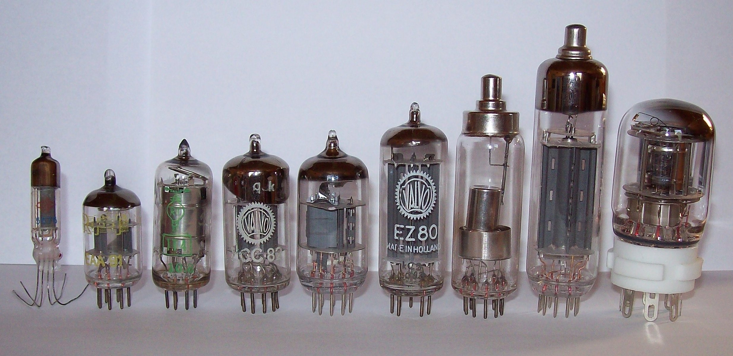
A vacuum tube, electron tube, valve (British usage), or tube (North America), is a device that controls electric current flow in a high vacuum between electrodes to which an electric voltage, potential difference has been applied. The type known as a thermionic tube or thermionic valve utilizes thermionic emission of electrons from a hot cathode for fundamental electronic functions such as signal amplifier, amplification and current rectifier, rectification. Non-thermionic types such as a vacuum phototube, however, achieve electron emission through the photoelectric effect, and are used for such purposes as the detection of light intensities. In both types, the electrons are accelerated from the cathode to the anode by the electric field in the tube. The simplest vacuum tube, the diode (i.e. Fleming valve), invented in 1904 by John Ambrose Fleming, contains only a heated electron-emitting cathode and an anode. Electrons can only flow in one direction through the device—fro ... [...More Info...] [...Related Items...] OR: [Wikipedia] [Google] [Baidu] |


