|
Timing Diagram (Unified Modeling Language)
A timing diagramOMG (2011)OMG Unified Modeling Language (OMG UML), Superstructure, V2.4.1 p. 546. in the Unified Modeling Language 2.0 is a specific type of interaction diagram, where the focus is on timing constraints. Timing diagrams are used to explore the behaviors of objects throughout a given period of time. A timing diagram is a special form of a sequence diagram A sequence diagram or system sequence diagram (SSD) shows process interactions arranged in time sequence in the field of software engineering. It depicts the processes involved and the sequence of messages exchanged between the processes needed .... The differences between timing diagram and sequence diagram are the axes are reversed so that the time increases from left to right and the lifelines are shown in separate compartments arranged vertically. There are two basic flavors of timing diagram: the ''concise notation'', and the ''robust notation'' . References External links Introduction to UML 2 T ... [...More Info...] [...Related Items...] OR: [Wikipedia] [Google] [Baidu] |
Unified Modeling Language
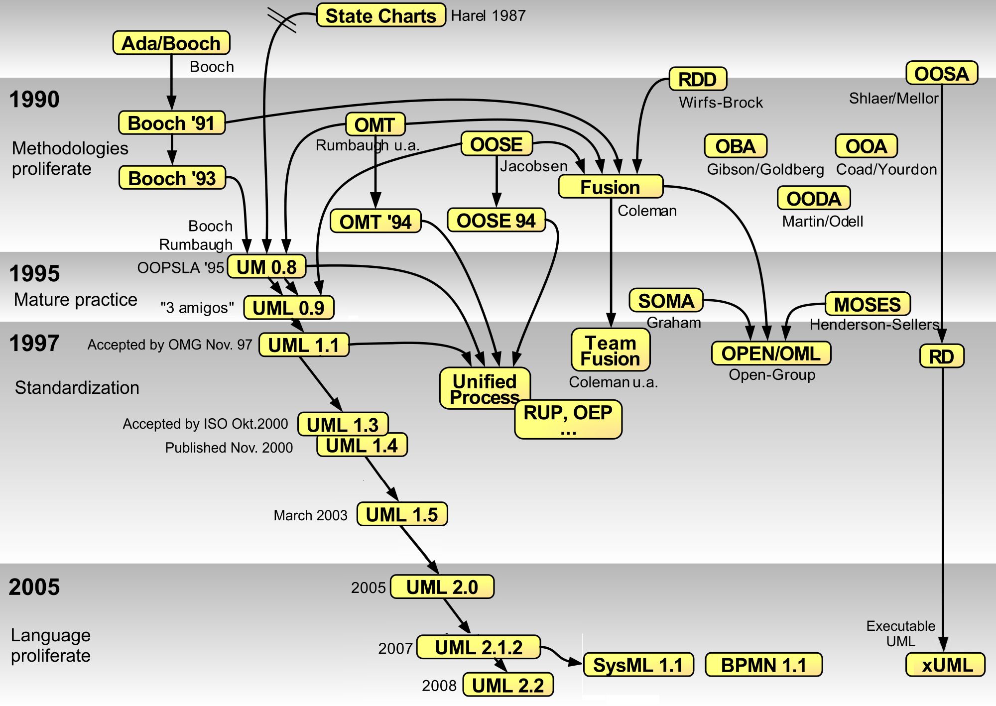
The Unified Modeling Language (UML) is a general-purpose, developmental modeling language in the field of software engineering that is intended to provide a standard way to visualize the design of a system. The creation of UML was originally motivated by the desire to standardize the disparate notational systems and approaches to software design. It was developed at Rational Software in 1994–1995, with further development led by them through 1996. In 1997, UML was adopted as a standard by the Object Management Group (OMG), and has been managed by this organization ever since. In 2005, UML was also published by the International Organization for Standardization (ISO) as an approved ISO standard. Since then the standard has been periodically revised to cover the latest revision of UML. In software engineering, most practitioners do not use UML, but instead produce informal hand drawn diagrams; these diagrams, however, often include elements from UML. History Before UM ... [...More Info...] [...Related Items...] OR: [Wikipedia] [Google] [Baidu] |
Interaction Diagram
The Unified Modeling Language (UML) is a general-purpose, developmental modeling language in the field of software engineering that is intended to provide a standard way to visualize the design of a system. The creation of UML was originally motivated by the desire to standardize the disparate notational systems and approaches to software design. It was developed at Rational Software in 1994–1995, with further development led by them through 1996. In 1997, UML was adopted as a standard by the Object Management Group (OMG), and has been managed by this organization ever since. In 2005, UML was also published by the International Organization for Standardization (ISO) as an approved ISO standard. Since then the standard has been periodically revised to cover the latest revision of UML. In software engineering, most practitioners do not use UML, but instead produce informal hand drawn diagrams; these diagrams, however, often include elements from UML. History Before UML 1 ... [...More Info...] [...Related Items...] OR: [Wikipedia] [Google] [Baidu] |
Behavior
Behavior (American English) or behaviour ( British English) is the range of actions and mannerisms made by individuals, organisms, systems or artificial entities in some environment. These systems can include other systems or organisms as well as the inanimate physical environment. It is the computed response of the system or organism to various stimuli or inputs, whether internal or external, conscious or subconscious, overt or covert, and voluntary or involuntary. Taking a behavior informatics perspective, a behavior consists of actor, operation, interactions, and their properties. This can be represented as a behavior vector. Models Biology Although disagreement exists as to how to precisely define behavior in a biological context, one common interpretation based on a meta-analysis of scientific literature states that "behavior is the internally coordinated responses (actions or inactions) of whole living organisms (individuals or groups) to internal and/or exte ... [...More Info...] [...Related Items...] OR: [Wikipedia] [Google] [Baidu] |
Object (computer Science)
In computer science, an object can be a variable, a data structure, a function, or a method. As regions of memory, they contain value and are referenced by identifiers. In the object-oriented programming paradigm, ''object'' can be a combination of variables, functions, and data structures; in particular in class-based variations of the paradigm it refers to a particular instance of a class. In the relational model of database management, an object can be a table or column, or an association between data and a database entity (such as relating a person's age to a specific person). Object-based languages An important distinction in programming languages is the difference between an object-oriented language and an object-based language. A language is usually considered object-based if it includes the basic capabilities for an object: identity, properties, and attributes. A language is considered object-oriented if it is object-based and also has the capability of polymor ... [...More Info...] [...Related Items...] OR: [Wikipedia] [Google] [Baidu] |
Sequence Diagram
A sequence diagram or system sequence diagram (SSD) shows process interactions arranged in time sequence in the field of software engineering. It depicts the processes involved and the sequence of messages exchanged between the processes needed to carry out the functionality. Sequence diagrams are typically associated with use case realizations in the 4+1 architectural view model of the system under development. Sequence diagrams are sometimes called event diagrams or event scenarios. For a particular scenario of a use case, the diagrams show the events that external actors generate, their order, and possible inter-system events. All systems are treated as a black box; the diagram places emphasis on events that cross the system boundary from actors to systems. A system sequence diagram should be done for the main success scenario of the use case, and frequent or complex alternative scenarios. Key elements of sequence diagram A sequence diagram shows, as parallel vertical lines ... [...More Info...] [...Related Items...] OR: [Wikipedia] [Google] [Baidu] |
