|
RL Circuit
A resistor–inductor circuit (RL circuit), or RL filter or RL network, is an electric circuit composed of resistors and inductors driven by a voltage or current source. A first-order RL circuit is composed of one resistor and one inductor, either in series driven by a voltage source or in parallel driven by a current source. It is one of the simplest analogue infinite impulse response electronic filters. Introduction The fundamental passive linear circuit elements are the resistor (R), capacitor (C) and inductor (L). These circuit elements can be combined to form an electrical circuit in four distinct ways: the RC circuit, the RL circuit, the LC circuit and the RLC circuit, with the abbreviations indicating which components are used. These circuits exhibit important types of behaviour that are fundamental to analogue electronics. In particular, they are able to act as passive filters. In practice, however, capacitors (and RC circuits) are usually preferred to inductors since t ... [...More Info...] [...Related Items...] OR: [Wikipedia] [Google] [Baidu] |
Electric Circuit
An electrical network is an interconnection of electrical components (e.g., batteries, resistors, inductors, capacitors, switches, transistors) or a model of such an interconnection, consisting of electrical elements (e.g., voltage sources, current sources, resistances, inductances, capacitances). An electrical circuit is a network consisting of a closed loop, giving a return path for the current. Linear electrical networks, a special type consisting only of sources (voltage or current), linear lumped elements (resistors, capacitors, inductors), and linear distributed elements (transmission lines), have the property that signals are linearly superimposable. They are thus more easily analyzed, using powerful frequency domain methods such as Laplace transforms, to determine DC response, AC response, and transient response. A resistive circuit is a circuit containing only resistors and ideal current and voltage sources. Analysis of resistive circuits is less complicated ... [...More Info...] [...Related Items...] OR: [Wikipedia] [Google] [Baidu] |
Complex Impedance
In electrical engineering, impedance is the opposition to alternating current presented by the combined effect of resistance and reactance in a circuit. Quantitatively, the impedance of a two-terminal circuit element is the ratio of the complex representation of the sinusoidal voltage between its terminals, to the complex representation of the current flowing through it. In general, it depends upon the frequency of the sinusoidal voltage. Impedance extends the concept of resistance to alternating current (AC) circuits, and possesses both magnitude and phase, unlike resistance, which has only magnitude. Impedance can be represented as a complex number, with the same units as resistance, for which the SI unit is the ohm (). Its symbol is usually , and it may be represented by writing its magnitude and phase in the polar form . However, Cartesian complex number representation is often more powerful for circuit analysis purposes. The notion of impedance is useful for perf ... [...More Info...] [...Related Items...] OR: [Wikipedia] [Google] [Baidu] |
Pole (complex Analysis)
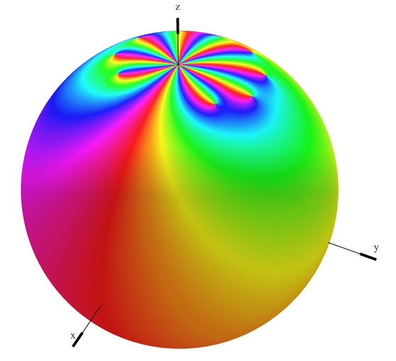
In complex analysis (a branch of mathematics), a pole is a certain type of singularity of a complex-valued function of a complex variable. In some sense, it is the simplest type of singularity. Technically, a point is a pole of a function if it is a zero of the function and is holomorphic in some neighbourhood of (that is, complex differentiable in a neighbourhood of ). A function is meromorphic in an open set if for every point of there is a neighborhood of in which either or is holomorphic. If is meromorphic in , then a zero of is a pole of , and a pole of is a zero of . This induces a duality between ''zeros'' and ''poles'', that is fundamental for the study of meromorphic functions. For example, if a function is meromorphic on the whole complex plane plus the point at infinity, then the sum of the multiplicities of its poles equals the sum of the multiplicities of its zeros. Definitions A function of a complex variable is holomorphic in an op ... [...More Info...] [...Related Items...] OR: [Wikipedia] [Google] [Baidu] |
Transfer Function
In engineering, a transfer function (also known as system function or network function) of a system, sub-system, or component is a mathematical function that theoretically models the system's output for each possible input. They are widely used in electronics and control systems. In some simple cases, this function is a two-dimensional graph of an independent scalar input versus the dependent scalar output, called a transfer curve or characteristic curve. Transfer functions for components are used to design and analyze systems assembled from components, particularly using the block diagram technique, in electronics and control theory. The dimensions and units of the transfer function model the output response of the device for a range of possible inputs. For example, the transfer function of a two-port electronic circuit like an amplifier might be a two-dimensional graph of the scalar voltage at the output as a function of the scalar voltage applied to the input; the transfer ... [...More Info...] [...Related Items...] OR: [Wikipedia] [Google] [Baidu] |
Voltage
Voltage, also known as electric pressure, electric tension, or (electric) potential difference, is the difference in electric potential between two points. In a static electric field, it corresponds to the work needed per unit of charge to move a test charge between the two points. In the International System of Units, the derived unit for voltage is named '' volt''. The voltage between points can be caused by the build-up of electric charge (e.g., a capacitor), and from an electromotive force (e.g., electromagnetic induction in generator, inductors, and transformers). On a macroscopic scale, a potential difference can be caused by electrochemical processes (e.g., cells and batteries), the pressure-induced piezoelectric effect, and the thermoelectric effect. A voltmeter can be used to measure the voltage between two points in a system. Often a common reference potential such as the ground of the system is used as one of the points. A voltage can represent eith ... [...More Info...] [...Related Items...] OR: [Wikipedia] [Google] [Baidu] |

