|
Green Satin Radar
Green Satin, also known as ARI 5851, was a Doppler radar system developed by the Royal Air Force as an air navigation aid. The system provided direct measures of the drift speed and direction, and thereby allowed accurate calculation of the winds aloft. These values were then fed into the Navigation and Bombing System. It was originally specified in 1949 as OR.3015 for the English Electric Canberra bomber. The first examples arrived in 1953, and it was soon fit operationally. It was subsequently used on the V bomber fleet. It remained in use on the V-bombers until the Avro Vulcans 1969 when it was replaced by the Decca 73. Handley Page Victors may have used it until they left service in 1993. The name comes from an era when the Ministry of Supply used random combinations of colours and code words to prevent their code names being too literal. A version known as Blue Silk with lower top-speed limits was used in some marks of Canberra and Royal Navy aircraft. Background In air navi ... [...More Info...] [...Related Items...] OR: [Wikipedia] [Google] [Baidu] |
Doppler Radar
A Doppler radar is a specialized radar that uses the Doppler effect to produce velocity data about objects at a distance. It does this by bouncing a microwave signal off a desired target and analyzing how the object's motion has altered the frequency of the returned signal. This variation gives direct and highly accurate measurements of the radial component of a target's velocity relative to the radar. Concept Doppler effect The Doppler effect (or Doppler shift), named after Austrian physicist Christian Doppler who proposed it in 1842, is the difference between the observed frequency and the emitted frequency of a wave for an observer moving relative to the source of the waves. It is commonly heard when a vehicle sounding a siren approaches, passes and recedes from an observer. The received frequency is higher (compared to the emitted frequency) during the approach, it is identical at the instant of passing by, and it is lower during the recession. This variation of f ... [...More Info...] [...Related Items...] OR: [Wikipedia] [Google] [Baidu] |
Drift Meter
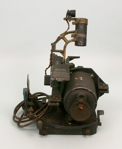
A drift meter, also drift indicator and drift sight, is an optical device used to improve dead reckoning for aircraft navigation by measuring wind effect on flight. Design A drift meter consists of a small telescope extended vertically through the bottom of the aircraft with the eyepiece inside the fuselage at the navigator's station. A reticle, typically consisting of spaced parallel lines, is rotated until objects on the ground are seen to be moving parallel to the vertical lines. The angle of the reticle then indicates the aircraft's drift angle due to winds aloft. It is also used to calculate the ground speed by measuring the time it takes for an object on the ground to pass from the upper to the lower horizontal line of the reticle. History Drift meters were extensively used in World War II by bomber aircraft. Typically, fighter aircraft were not equipped with this kind of relatively sophisticated navigational equipment. For instance, in the Pacific Theater, where navigation ... [...More Info...] [...Related Items...] OR: [Wikipedia] [Google] [Baidu] |
Star Tracker
A star tracker is an optical device that measures the positions of stars using photocells or a camera. As the positions of many stars have been measured by astronomers to a high degree of accuracy, a star tracker on a satellite or spacecraft may be used to determine the orientation (or attitude) of the spacecraft with respect to the stars. In order to do this, the star tracker must obtain an image of the stars, measure their apparent position in the reference frame of the spacecraft, and identify the stars so their position can be compared with their known absolute position from a star catalog. A star tracker may include a processor to identify stars by comparing the pattern of observed stars with the known pattern of stars in the sky. History In the 1950s and early 1960s, star trackers were an important part of early long-range ballistic missiles and cruise missiles, in the era when inertial navigation systems (INS) were not sufficiently accurate for intercontinental ranges. C ... [...More Info...] [...Related Items...] OR: [Wikipedia] [Google] [Baidu] |
Mark XIV Bomb Sight
The Mark XIV Bomb Sight was a bombsight developed by Royal Air Force (RAF) Bomber Command during the Second World War. It was also known as the Blackett sight after its primary inventor, P. M. S. Blackett. Production of a slightly modified version was also undertaken in the United States as the Sperry T-1, which was interchangeable with the UK-built version. It was the RAF's standard bombsight for the second half of the war. Developed starting in 1939, the Mk. XIV began replacing the First World War–era Course Setting Bomb Sight in 1942. The Mk. XIV was essentially an automated version of the Course Setting sight, using a mechanical computer to update the sights in real-time as conditions changed. The Mk. XIV required only 10 seconds of straight flight before the drop and automatically accounted for shallow climbs and dives. More importantly, the Mk. XIV sighting unit was much smaller than the Course Setting sight, which allowed it to contain a gyro stabilization platform. ... [...More Info...] [...Related Items...] OR: [Wikipedia] [Google] [Baidu] |
H2S Radar
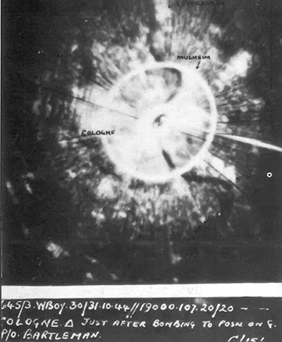
H2S was the first airborne, ground scanning radar system. It was developed for the Royal Air Force's Bomber Command during World War II to identify targets on the ground for night and all-weather bombing. This allowed attacks outside the range of the various radio navigation aids like Gee or Oboe, which were limited to about . It was also widely used as a general navigation system, allowing landmarks to be identified at long range. In March 1941, experiments with an early airborne interception radar based on the 9.1 cm wavelength, (3 GHz) cavity magnetron revealed that different objects have very different radar signatures; water, open land and built-up areas of cities and towns all produced distinct returns. In January 1942, a new team was set up to combine the magnetron with a new scanning antenna and plan-position indicator display. The prototype's first use in April confirmed that a map of the area below the aircraft could be produced using radar. The first systems ... [...More Info...] [...Related Items...] OR: [Wikipedia] [Google] [Baidu] |
Mechanical Computer
A mechanical computer is a computer built from mechanical components such as levers and gears rather than electronic components. The most common examples are adding machines and mechanical counters, which use the turning of gears to increment output displays. More complex examples could carry out multiplication and division—Friden used a moving head which paused at each column—and even differential analysis. One model, the Ascota 170 accounting machine sold in the 1960s calculated square roots. Mechanical computers can be either analog, using smooth mechanisms such as curved plates or slide rules for computations; or digital, which use gears. Mechanical computers reached their zenith during World War II, when they formed the basis of complex bombsights including the Norden, as well as the similar devices for ship computations such as the US Torpedo Data Computer or British Admiralty Fire Control Table. Noteworthy are mechanical flight instruments for early spacecraft, which ... [...More Info...] [...Related Items...] OR: [Wikipedia] [Google] [Baidu] |
Klystron
A klystron is a specialized linear-beam vacuum tube, invented in 1937 by American electrical engineers Russell and Sigurd Varian,Pond, Norman H. "The Tube Guys". Russ Cochran, 2008 p.31-40 which is used as an amplifier for high radio frequencies, from UHF up into the microwave range. Low-power klystrons are used as oscillators in terrestrial microwave relay communications links, while high-power klystrons are used as output tubes in UHF television transmitters, satellite communication, radar transmitters, and to generate the drive power for modern particle accelerators. In a klystron, an electron beam interacts with radio waves as it passes through resonant cavities, metal boxes along the length of a tube. The electron beam first passes through a cavity to which the input signal is applied. The energy of the electron beam amplifies the signal, and the amplified signal is taken from a cavity at the other end of the tube. The output signal can be coupled back into the input cavi ... [...More Info...] [...Related Items...] OR: [Wikipedia] [Google] [Baidu] |
Cavity Magnetron
The cavity magnetron is a high-power vacuum tube used in early radar systems and currently in microwave ovens and linear particle accelerators. It generates microwaves using the interaction of a stream of electrons with a magnetic field while moving past a series of cavity resonators, which are small, open cavities in a metal block. Electrons pass by the cavities and cause microwaves to oscillate within, similar to the functioning of a whistle producing a tone when excited by an air stream blown past its opening. The resonant frequency of the arrangement is determined by the cavities' physical dimensions. Unlike other vacuum tubes, such as a klystron or a traveling-wave tube (TWT), the magnetron cannot function as an amplifier for increasing the intensity of an applied microwave signal; the magnetron serves solely as an oscillator, generating a microwave signal from direct current electricity supplied to the vacuum tube. The use of magnetic fields as a means to control the f ... [...More Info...] [...Related Items...] OR: [Wikipedia] [Google] [Baidu] |
Monopulse Radar
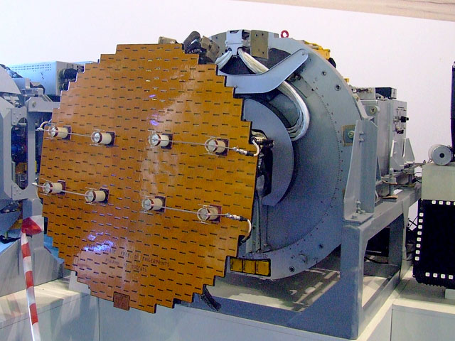
Monopulse radar is a radar system that uses additional encoding of the radio signal to provide accurate directional information. The name refers to its ability to extract range and direction from a single signal pulse. Monopulse radar avoids problems seen in conical scanning radar systems, which can be confused by rapid changes in signal strength. The system also makes electronic warfare, jamming more difficult. Most radars designed since the 1960s are monopulse systems. The monopulse method is also used in passive systems, such as electronic support measures and radio astronomy. Monopulse radar systems can be constructed with reflector (antenna) , reflector antennas, lens antenna , lens antennas or array antennas. Historically, monopulse systems have been classified as either phase-comparison monopulse or amplitude monopulse. Modern systems determine the direction from the monopulse ratio, which contain both amplitude and phase information. The monopulse method does not requir ... [...More Info...] [...Related Items...] OR: [Wikipedia] [Google] [Baidu] |
Pulse-Doppler Radar
A pulse-Doppler radar is a radar system that determines the range to a target using pulse-timing techniques, and uses the Doppler effect of the returned signal to determine the target object's velocity. It combines the features of pulse radars and continuous-wave radars, which were formerly separate due to the complexity of the electronics. The first operational Pulse Doppler radar was in the CIM-10 Bomarc, an American long range supersonic missile powered by ramjet engines, and which was armed with a W40 nuclear weapon to destroy entire formations of attacking enemy aircraft. Pulse-Doppler systems were first widely used on fighter aircraft starting in the 1960s. Earlier radars had used pulse-timing in order to determine range and the angle of the antenna (or similar means) to determine the bearing. However, this only worked when the radar antenna was not pointed down; in that case the reflection off the ground overwhelmed any returns from other objects. As the ground moves at the ... [...More Info...] [...Related Items...] OR: [Wikipedia] [Google] [Baidu] |
Voltage
Voltage, also known as electric pressure, electric tension, or (electric) potential difference, is the difference in electric potential between two points. In a static electric field, it corresponds to the work needed per unit of charge to move a test charge between the two points. In the International System of Units, the derived unit for voltage is named ''volt''. The voltage between points can be caused by the build-up of electric charge (e.g., a capacitor), and from an electromotive force (e.g., electromagnetic induction in generator, inductors, and transformers). On a macroscopic scale, a potential difference can be caused by electrochemical processes (e.g., cells and batteries), the pressure-induced piezoelectric effect, and the thermoelectric effect. A voltmeter can be used to measure the voltage between two points in a system. Often a common reference potential such as the ground of the system is used as one of the points. A voltage can represent either a source ... [...More Info...] [...Related Items...] OR: [Wikipedia] [Google] [Baidu] |
Comparator
In electronics, a comparator is a device that compares two voltages or currents and outputs a digital signal indicating which is larger. It has two analog input terminals V_+ and V_- and one binary digital output V_\text. The output is ideally : V_\text = \begin 1, & \textV_+ > V_-, \\ 0, & \textV_+ < V_-. \end A comparator consists of a specialized high- . They are commonly used in devices that measure and digitize analog signals, such as s (ADCs), as well as |


.jpg)