|
GR Connector
The GR connector, officially the General Radio Type 874, was a type of RF connector used for connecting coaxial cable. Designed by Eduard Karplus, Harold M. Wilson and William R. Thurston at General Radio Corporation. It was widely used on General Radio's electronic test equipment and some Tektronix instruments from the 1950s to the 1970s. The connector had several desirable properties: * Good control of the electrical impedance across a wide range of frequencies, therefore low reflection * Reliable mating * Hermaphrodism, so there were no "male" or "female" connectors; any GR connector could mate with any other GR connector. This last characteristic was achieved by having both the inner and outer conductors made from four leaves, two of which were displaced slightly outwards and two of which were displaced slightly inwards. By rotating one connector by 90 degrees, its inner leaves would mate with the other connector's outer leaves and vice versa. When frequently mated, the inne ... [...More Info...] [...Related Items...] OR: [Wikipedia] [Google] [Baidu] |
RF Connector
A coaxial RF connector (radio frequency connector) is an electrical connector designed to work at radio frequencies in the multi-megahertz range. RF connectors are typically used with coaxial cables and are designed to maintain the shielding that the coaxial design offers. Better models also minimize the change in transmission line impedance at the connection in order to reduce signal reflection and power loss. As the frequency increases, transmission line effects become more important, with small impedance variations from connectors causing the signal to reflect rather than pass through. An RF connector must not allow external signals into the circuit through electromagnetic interference and capacitive pickup. Mechanically, RF connectors may provide a fastening mechanism ( thread, bayonet, braces, blind mate) and springs for a low ohmic electric contact while sparing the gold surface, thus allowing very high mating cycles and reducing the insertion force. Research activit ... [...More Info...] [...Related Items...] OR: [Wikipedia] [Google] [Baidu] |
General Radio
General Radio Company (later, GenRad) was a broad-line manufacturer of electronic test equipment in Massachusetts, U.S. from 1915 to 2001. History On June 14, 1915, Melville Eastham and a small group of investors started General Radio Company in Cambridge, Massachusetts, a few blocks northwest of Massachusetts Institute of Technology. During the 1950s, the company moved to West Concord, Massachusetts, where it became a major player in the automatic test equipment (ATE) business, manufacturing a line of testers for assembled printed circuit boards. It also produced extensive lines of electrical component measuring equipment, sound and vibration measurement and RLC standards. In 1975, the company name was changed to GenRad. In 1991, a startup QuadTech was founded as spinoff of GenRad's Instrumentation division and Precision Product lines, as well as the rights to use the "GenRad" and "General Radio" names. In 2000, IET Labs acquired from QuadTech the GenRad RLC standards, imp ... [...More Info...] [...Related Items...] OR: [Wikipedia] [Google] [Baidu] |
Coaxial
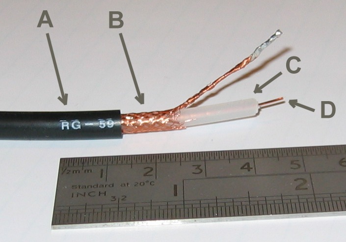
In geometry, coaxial means that several three-dimensional linear or planar forms share a common axis. The two-dimensional analog is ''concentric''. Common examples: A coaxial cable is a three-dimensional linear structure. It has a wire conductor in the centre (D), a circumferential outer conductor (B), and an insulating medium called the dielectric (C) separating these two conductors. The outer conductor is usually sheathed in a protective PVC outer jacket (A). All these have a common axis. The dimension and material of the conductors and insulation determine the cable's characteristic impedance and attenuation at various frequencies. Coaxial rotors are a three-dimensional planar structure: a pair of helicopter rotors (wings) mounted one above the other on concentric shafts, with the same axis of rotation (but turning in opposite directions). In loudspeaker design, coaxial speakers A coaxial loudspeaker is a loudspeaker system in which the individual driver units radiate s ... [...More Info...] [...Related Items...] OR: [Wikipedia] [Google] [Baidu] |
Coaxial Cable
Coaxial cable, or coax (pronounced ) is a type of electrical cable consisting of an inner conductor surrounded by a concentric conducting shield, with the two separated by a dielectric ( insulating material); many coaxial cables also have a protective outer sheath or jacket. The term ''coaxial'' refers to the inner conductor and the outer shield sharing a geometric axis. Coaxial cable is a type of transmission line, used to carry high-frequency electrical signals with low losses. It is used in such applications as telephone trunk lines, broadband internet networking cables, high-speed computer data busses, cable television signals, and connecting radio transmitters and receivers to their antennas. It differs from other shielded cables because the dimensions of the cable and connectors are controlled to give a precise, constant conductor spacing, which is needed for it to function efficiently as a transmission line. Coaxial cable was used in the first (1858) and followin ... [...More Info...] [...Related Items...] OR: [Wikipedia] [Google] [Baidu] |
Eduard Karplus
Eduard Karplus (September 7, 1899 – August ?, 1979) was an Austrian-born engineer, best known as the inventor of the Variac. Karplus was born in Hinterbrühl, the second child of Johann Paul Karplus, a neurophysiologist and psychiatrist, and Valerie von Lieben, a sister of physicist Robert von Lieben. He had three brothers, Johann (Hans) Karplus (father of 2013 Nobel Laureate in Chemistry, Martin Karplus), Walter Gottlieb Karplus and Heinrich Karplus. Eduard attended Gymnasium Stubenbastei in Vienna, completing with Matura in 1918, and graduated as "Diplomingenieur" from the Electrical Engineering department of the Vienna University of Technology in 1923. From 1923 to 1929, he was employed in the radio frequency laboratories of the C. Lorenz AG, Berlin, Germany, where he worked on mobile high-frequency communication equipment. In 1930, Eduard Karplus joined the engineering staff of General Radio Corporation in Cambridge, Massachusetts, where he designed and develo ... [...More Info...] [...Related Items...] OR: [Wikipedia] [Google] [Baidu] |
Electronic Test Equipment
Electronic test equipment is used to create signals and capture responses from electronic devices under test (DUTs). In this way, the proper operation of the DUT can be proven or faults in the device can be traced. Use of electronic test equipment is essential to any serious work on electronics systems. Practical electronics engineering and assembly requires the use of many different kinds of electronic test equipment ranging from the very simple and inexpensive (such as a test light consisting of just a light bulb and a test lead) to extremely complex and sophisticated such as automatic test equipment (ATE). ATE often includes many of these instruments in real and simulated forms. Generally, more advanced test gear is necessary when developing circuits and systems than is needed when doing production testing or when troubleshooting existing production units in the field. Types of test equipment Basic equipment The following items are used for basic measurement of voltages, cu ... [...More Info...] [...Related Items...] OR: [Wikipedia] [Google] [Baidu] |
Tektronix
Tektronix, Inc., historically widely known as Tek, is an American company best known for manufacturing test and measurement devices such as oscilloscopes, logic analyzers, and video and mobile test protocol equipment. Originally an independent company, it is now a subsidiary of Fortive, a spinoff from Danaher Corporation. Several charities are, or were, associated with Tektronix, including the Tektronix Foundation and the M.J. Murdock Charitable Trust in Vancouver, Washington. History 1946–1954 The company traces its roots to the electronics revolution that immediately followed World War II. It was founded in December 1945 as Tekrad. The name was similar to that of a California company, Techrad, so in 1946, the four partners, Howard Vollum, Jack Murdock and Miles Tippery, who had both served in the Coast Guard, and accountant Glenn McDowell, formed Tektronix, Inc. Each contributed an initial $2,600 for equal shares. Howard Vollum had graduated in 1936 from Reed Coll ... [...More Info...] [...Related Items...] OR: [Wikipedia] [Google] [Baidu] |
Electrical Impedance
In electrical engineering, impedance is the opposition to alternating current presented by the combined effect of resistance and reactance in a circuit. Quantitatively, the impedance of a two-terminal circuit element is the ratio of the complex representation of the sinusoidal voltage between its terminals, to the complex representation of the current flowing through it. In general, it depends upon the frequency of the sinusoidal voltage. Impedance extends the concept of resistance to alternating current (AC) circuits, and possesses both magnitude and phase, unlike resistance, which has only magnitude. Impedance can be represented as a complex number, with the same units as resistance, for which the SI unit is the ohm (). Its symbol is usually , and it may be represented by writing its magnitude and phase in the polar form . However, Cartesian complex number representation is often more powerful for circuit analysis purposes. The notion of impedance is useful for perf ... [...More Info...] [...Related Items...] OR: [Wikipedia] [Google] [Baidu] |
Hermaphroditic Connector
In electrical and machine, mechanical trades and manufacturing, each half of a pair of mating Electrical connector, connectors or fasteners is conventionally assigned the designation male or female. The female connector is generally a AC power plugs and sockets, receptacle that receives and holds the male connector. Sometimes the terms plug and socket or jack are used, particularly in reference to Electrical connector#Jacks and plugs, electrical connectors. In some cases, the pins on the connector may have the opposite nominal gender to the mounted connector, such as the RCA connector. The assignment is a direct analogy with male/female Sex organ, genitalia, the part bearing one or more protrusions or which fits inside the other being designated male, in contrast to the part containing the corresponding indentations, or fitting outside the other, being designated female. Extension of the analogy results in the verb to mating, mate being used to describe the process of connecting ... [...More Info...] [...Related Items...] OR: [Wikipedia] [Google] [Baidu] |
APC-7 Connector
The APC-7 connector (also referred to as a 7 mm connector) is a precision coaxial connector used on laboratory microwave test equipment for frequencies up to 18 GHz. APC-7 connectors are advantageous because they have a low-reflection coefficient, make repeatable coaxial connections, and are genderless. The connectors are expensive, so they are seldom used outside the laboratory where their cost can be justified by their accuracy and convenience. Due to their high cost, their 18 GHz frequency limitation, and new laboratory practices,Connections at the instrument front panel don't need to be repeatable because those connections remain mated during tests. Modern network analyzers focus on the reference plane near the device under test and have features such as automated calibration, adapter removal, and models for calibration references. The advantages of the APC-7 connector have been diminished. the connectors are now uncommon. Modern low frequency microwave equipme ... [...More Info...] [...Related Items...] OR: [Wikipedia] [Google] [Baidu] |
N Connector
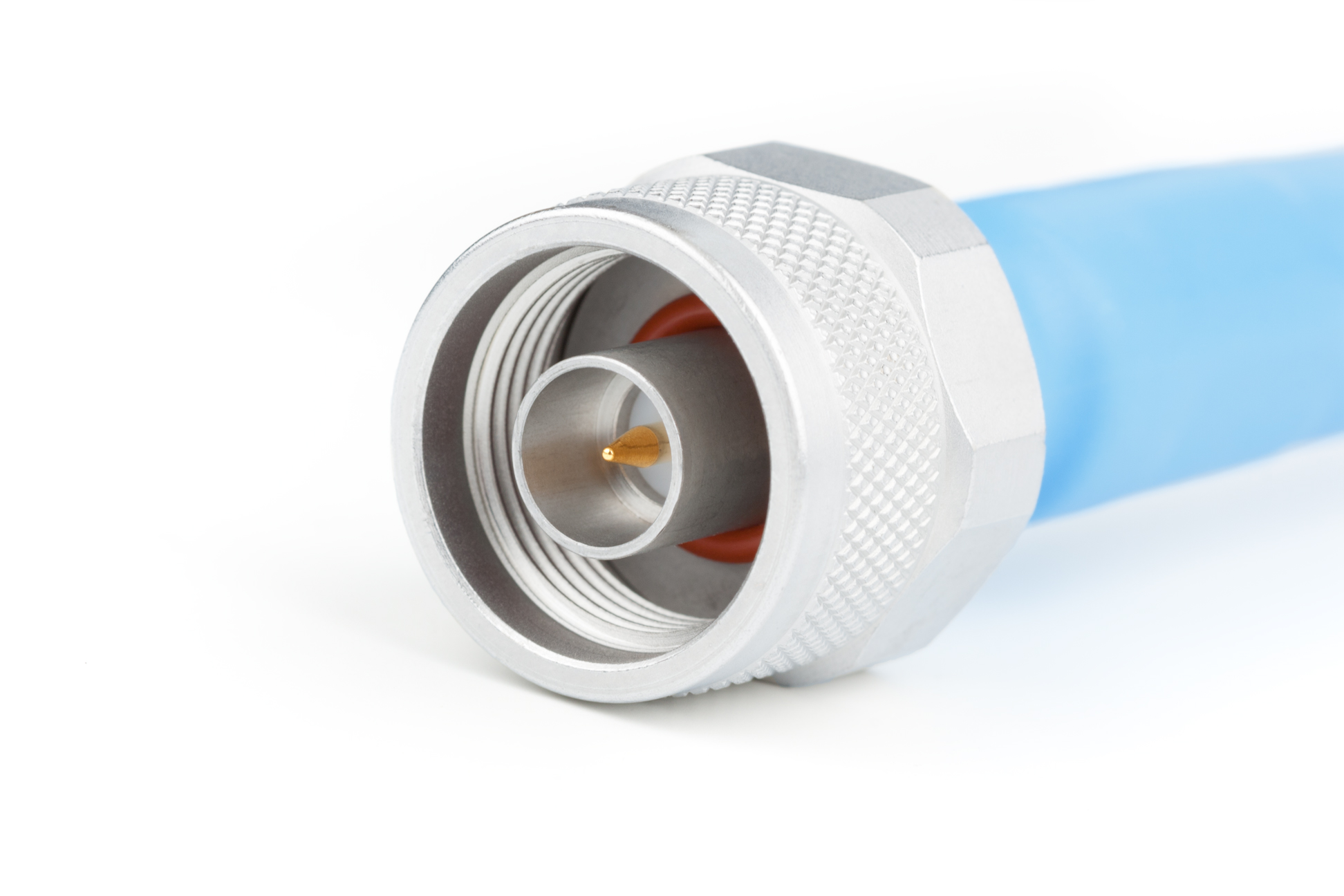
The N connector (also, type-N connector) is a threaded, weatherproof, medium-size RF connector used to join coaxial cables. It was one of the first connectors capable of carrying microwave-frequency signals, and was invented in the 1940s by Paul Neill of Bell Labs, after whom the connector is named. Design The interface specifications for the N and many other connectors are referenced in MIL-STD-348. Originally, the connector was designed to carry signals at frequencies up to 1 GHz in military applications, but today's common Type N easily handles frequencies up to 11 GHz. More recent precision enhancements to the design by Julius Botka at Hewlett Packard have pushed this to 18 GHz. The male connector is hand-tightened (though versions with a hex nut are also available) and has an air gap between the center and outer conductors. The coupling has a -24 UNEF thread. Amphenol suggests tightening to a torque of , while Andrew Corporation suggest for their hex nut ... [...More Info...] [...Related Items...] OR: [Wikipedia] [Google] [Baidu] |


