|
Command And Data Modes (modem)
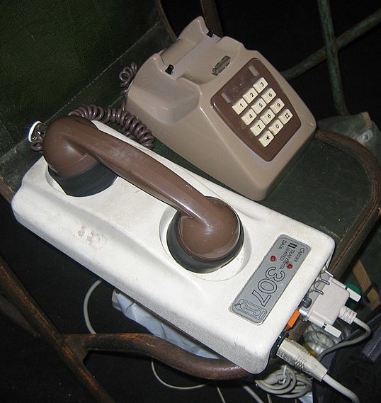
Command and Data modes refer to the two modes in which a computer modem may operate. These modes are defined in the Hayes command set, which is the de facto standard for all modems. These modes exist because there is only one channel of communication between the modem and the computer, which must carry both the computer's commands to the modem, as well as the data that the modem is enlisted to transmit to the remote party over the telephone line. When a modem is in command mode, any characters sent to it are interpreted as commands for the modem to execute, per the Hayes command set. A command is preceded by the letters 'AT', which stand for 'Attention'. For example, if a modem receives 'ATDT5551212' while in the command mode, it interprets that as an instruction to dial the numbers 5551212 on the telephone, using touch-tone dialing. While in command mode, the modem may send responses back to the computer indicating the outcome of the command. For example, the modem may respo ... [...More Info...] [...Related Items...] OR: [Wikipedia] [Google] [Baidu] |
Modem
A modulator-demodulator or modem is a computer hardware device that converts data from a digital format into a format suitable for an analog transmission medium such as telephone or radio. A modem transmits data by Modulation#Digital modulation methods, modulating one or more carrier wave signals to encode digital information, while the receiver Demodulation, demodulates the signal to recreate the original digital information. The goal is to produce a Signal (electronics), signal that can be transmitted easily and decoded reliably. Modems can be used with almost any means of transmitting analog signals, from light-emitting diodes to radio. Early modems were devices that used audible sounds suitable for transmission over traditional telephone systems and leased lines. These generally operated at 110 or 300 bits per second (bit/s), and the connection between devices was normally manual, using an attached telephone handset. By the 1970s, higher speeds of 1,200 and 2,400 ... [...More Info...] [...Related Items...] OR: [Wikipedia] [Google] [Baidu] |
Hayes Command Set
The Hayes command set (also known as the AT command set) is a specific command language originally developed by Dennis Hayes for the Hayes Smartmodem 300 baud modem in 1981. The command set consists of a series of short text strings which can be combined to produce commands for operations such as dialing, hanging up, and changing the parameters of the connection. The vast majority of dial-up modems use the Hayes command set in numerous variations. The command set covered only those operations supported by the earliest 300 bit/s modems. When new commands were required to control additional functionality in higher speed modems, a variety of one-off standards emerged from each of the major vendors. These continued to share the basic command structure and syntax, but added any number of new commands using some sort of prefix character – & for Hayes and USR, and \ for Microcom, for instance. Many of these were re-standardized on the Hayes extensions after the introduction of t ... [...More Info...] [...Related Items...] OR: [Wikipedia] [Google] [Baidu] |
Touch-tone
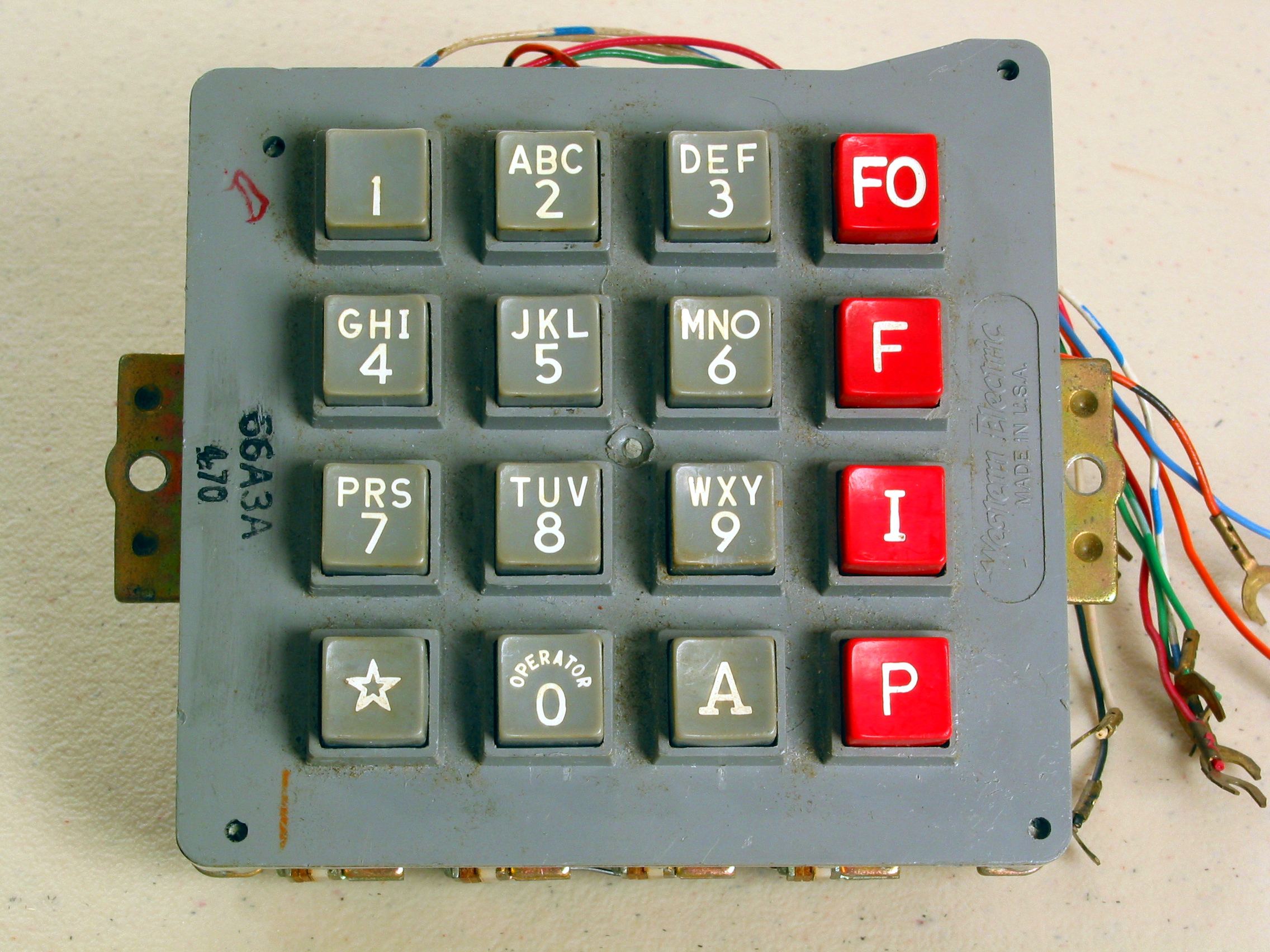
Dual-tone multi-frequency signaling (DTMF) is a telecommunication signaling system using the voice-frequency band over telephone lines between telephone equipment and other communications devices and switching centers. DTMF was first developed in the Bell System in the United States, and became known under the trademark Touch-Tone for use in push-button telephones supplied to telephone customers, starting in 1963. DTMF is standardized as ITU-T Recommendation Q.23. It is also known in the UK as ''MF4''. The Touch-Tone system using a telephone keypad gradually replaced the use of rotary dial and has become the industry standard for landline and mobile service. Other multi-frequency systems are used for internal signaling within the telephone network. Multifrequency signaling Before the development of DTMF, telephone numbers were dialed by users with a loop-disconnect (LD) signaling, more commonly known as pulse dialing (dial pulse, DP) in the United States. It functions by int ... [...More Info...] [...Related Items...] OR: [Wikipedia] [Google] [Baidu] |
Carriage Return
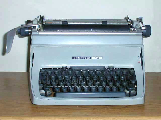
A carriage return, sometimes known as a cartridge return and often shortened to CR, or return, is a control character or mechanism used to reset a device's position to the beginning of a line of text. It is closely associated with the line feed and newline concepts, although it can be considered separately in its own right. Typewriters Originally, the term "carriage return" referred to a mechanism or lever on a typewriter. For machines where the type element was fixed and the paper held in a moving ''carriage'', this lever was on the left attached to the moving carriage, and operated after typing a line of text to cause the carriage to return to the far right so the type element would be aligned to the left side of the paper. The lever would also usually ''feed'' the paper to advance to the next line. Many electric typewriters such as IBM Electric or Underwood Electric made carriage return to be another key on the keyboard instead of a lever. The key was usually labeled "carri ... [...More Info...] [...Related Items...] OR: [Wikipedia] [Google] [Baidu] |
Data Terminal Ready
Data Terminal Ready (DTR) is a control signal in RS-232 serial communications, transmitted from data terminal equipment (DTE), such as a computer, to data communications equipment (DCE), for example a modem, to indicate that the terminal is ready for communications and the modem may initiate a communications channel. The DTR signal is present on pin 20 of the 22-wire RS-232 interface using a DB-25 connector, and on pin 4 of a newer DE-9 serial port. The signal is asserted (logic "1") by raising the voltage of the pin from negative to positive. Dropping the signal back to its negative state indicates to the modem that the communications session shall be terminated. Signaling for modems The DTR signal is an important call control signal for a data modem. According to the RS232 standard, dropping DTR from active to inactive for at least two seconds tells the modem to disconnect (end) a call or data connection. When a modem is being used for automatic answering (such as with the comm ... [...More Info...] [...Related Items...] OR: [Wikipedia] [Google] [Baidu] |
Data Carrier Detect
Data Carrier Detect, abbreviated as DCD, or alternately Carrier Detect abbreviated as CD, is a control signal present inside an RS-232 serial communications cable that goes between a computer and another device, such as a modem. This signal is a simple "high/low" status bit that is sent "from DCE to DTE", or in a typical scenario, from the peripheral to the computer. It is present on virtually all PC serial ports - pin 1 of a nine-pin ( DE9) serial port, or pin eight over a 25-pin (DB25) port. Its purpose varies depending on the device connected, but the most specific meaning is to indicate when a modem is connected to another remote modem via telephone lines. The word "carrier" is a reference to the analog carrier signal generated by a modem, which is modulated to carry the data. On a data modem, the carrier's loss equates to the connection's termination. Much like the Ring Indicator signal, on a PC's serial port, changes to the DCD signal state can generate a hardware interrupt ... [...More Info...] [...Related Items...] OR: [Wikipedia] [Google] [Baidu] |
C0 And C1 Control Codes
The C0 and C1 control code or control character sets define control codes for use in text by computer systems that use ASCII and derivatives of ASCII. The codes represent additional information about the text, such as the position of a cursor, an instruction to start a new line, or a message that the text has been received. C0 codes are the range 00 HEX–1FHEX and the default C0 set was originally defined in ISO 646 (ASCII). C1 codes are the range 80HEX–9FHEX and the default C1 set was originally defined in ECMA-48 (harmonized later with ISO 6429). The ISO/IEC 2022 system of specifying control and graphic characters allows other C0 and C1 sets to be available for specialized applications, but they are rarely used. C0 controls ASCII defined 32 control characters, plus a necessary extra character for the DEL character, 7FHEX or 01111111BIN (needed to punch out all the holes on a paper tape and erase it). This large number of codes was desirable at the time, as multi ... [...More Info...] [...Related Items...] OR: [Wikipedia] [Google] [Baidu] |
ASCII
ASCII ( ), abbreviated from American Standard Code for Information Interchange, is a character encoding standard for electronic communication. ASCII codes represent text in computers, telecommunications equipment, and other devices. Because of technical limitations of computer systems at the time it was invented, ASCII has just 128 code points, of which only 95 are , which severely limited its scope. All modern computer systems instead use Unicode, which has millions of code points, but the first 128 of these are the same as the ASCII set. The Internet Assigned Numbers Authority (IANA) prefers the name US-ASCII for this character encoding. ASCII is one of the List of IEEE milestones, IEEE milestones. Overview ASCII was developed from telegraph code. Its first commercial use was as a seven-bit teleprinter code promoted by Bell data services. Work on the ASCII standard began in May 1961, with the first meeting of the American Standards Association's (ASA) (now the American Nat ... [...More Info...] [...Related Items...] OR: [Wikipedia] [Google] [Baidu] |


