|
Class Of Accuracy In Electrical Measurements
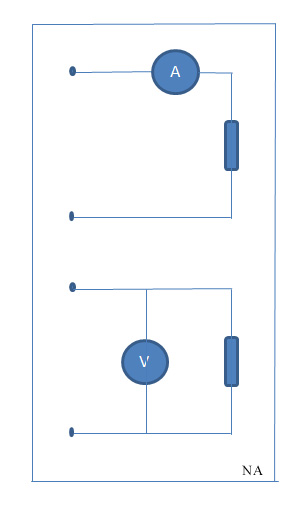
In electrical engineering class of accuracy is a figure which represents the error tolerance of a measuring device. Class of accuracy Measuring devices are labelled for the class of accuracy. This figure is the percentage of the inherent error of the measuring device with respect to full scale deflection. For example, if the class of accuracy is 2 that means an error of 2 volts in a full scale 100 volt reading. Measurement In electrical engineering, characteristics like current or voltage can be measured by an ammeter, a voltmeter, a multimeter A multimeter is a measuring instrument that can measure multiple electrical properties. A typical multimeter can measure voltage, resistance, and current, in which case it is also known as a volt-ohm-milliammeter (VOM), as the unit is equipped w ..., etc. The ammeter is used in series with the load, so the same current flows through the load and the ammeter. The voltmeter is used in parallel with the load, so the voltage between ... [...More Info...] [...Related Items...] OR: [Wikipedia] [Google] [Baidu] |
Voltmeter Ammeter
A voltmeter is an instrument used for measuring electric potential difference between two points in an electric circuit. It is connected in parallel. It usually has a high resistance so that it takes negligible current from the circuit. Analog voltmeters move a pointer across a scale in proportion to the voltage measured and can be built from a galvanometer and series resistor. Meters using amplifiers can measure tiny voltages of microvolts or less. Digital voltmeters give a numerical display of voltage by use of an analog-to-digital converter. Voltmeters are made in a wide range of styles, some separately powered (e.g. by battery), and others powered by the measured voltage source itself. Instruments permanently mounted in a panel are used to monitor generators or other fixed apparatus. Portable instruments, usually equipped to also measure current and resistance in the form of a multimeter, are standard test instruments used in electrical and electronics work. Any measurem ... [...More Info...] [...Related Items...] OR: [Wikipedia] [Google] [Baidu] |
Electric Current
An electric current is a stream of charged particles, such as electrons or ions, moving through an electrical conductor or space. It is measured as the net rate of flow of electric charge through a surface or into a control volume. The moving particles are called charge carriers, which may be one of several types of particles, depending on the conductor. In electric circuits the charge carriers are often electrons moving through a wire. In semiconductors they can be electrons or holes. In an electrolyte the charge carriers are ions, while in plasma, an ionized gas, they are ions and electrons. The SI unit of electric current is the ampere, or ''amp'', which is the flow of electric charge across a surface at the rate of one coulomb per second. The ampere (symbol: A) is an SI base unit. Electric current is measured using a device called an ammeter. Electric currents create magnetic fields, which are used in motors, generators, inductors, and transformers. In ... [...More Info...] [...Related Items...] OR: [Wikipedia] [Google] [Baidu] |
Voltage
Voltage, also known as electric pressure, electric tension, or (electric) potential difference, is the difference in electric potential between two points. In a static electric field, it corresponds to the work needed per unit of charge to move a test charge between the two points. In the International System of Units, the derived unit for voltage is named '' volt''. The voltage between points can be caused by the build-up of electric charge (e.g., a capacitor), and from an electromotive force (e.g., electromagnetic induction in generator, inductors, and transformers). On a macroscopic scale, a potential difference can be caused by electrochemical processes (e.g., cells and batteries), the pressure-induced piezoelectric effect, and the thermoelectric effect. A voltmeter can be used to measure the voltage between two points in a system. Often a common reference potential such as the ground of the system is used as one of the points. A voltage can represent either a ... [...More Info...] [...Related Items...] OR: [Wikipedia] [Google] [Baidu] |
Ammeter
An ammeter (abbreviation of ''Ampere meter'') is an instrument used to measure the current in a circuit. Electric currents are measured in amperes (A), hence the name. For direct measurement, the ammeter is connected in series with the circuit in which the current is to be measured. An ammeter usually has low resistance so that it does not cause a significant voltage drop in the circuit being measured. Instruments used to measure smaller currents, in the milliampere or microampere range, are designated as ''milliammeters'' or ''microammeters''. Early ammeters were laboratory instruments that relied on the Earth's magnetic field for operation. By the late 19th century, improved instruments were designed which could be mounted in any position and allowed accurate measurements in electric power systems. It is generally represented by letter 'A' in a circuit. History The relation between electric current, magnetic fields and physical forces was first noted by Hans Christian à ... [...More Info...] [...Related Items...] OR: [Wikipedia] [Google] [Baidu] |
Voltmeter
A voltmeter is an instrument used for measuring electric potential difference between two points in an electric circuit. It is connected in parallel. It usually has a high resistance so that it takes negligible current from the circuit. Analog voltmeters move a pointer across a scale in proportion to the voltage measured and can be built from a galvanometer and series resistor. Meters using amplifiers can measure tiny voltages of microvolts or less. Digital voltmeters give a numerical display of voltage by use of an analog-to-digital converter. Voltmeters are made in a wide range of styles, some separately powered (e.g. by battery), and others powered by the measured voltage source itself. Instruments permanently mounted in a panel are used to monitor generators or other fixed apparatus. Portable instruments, usually equipped to also measure current and resistance in the form of a multimeter, are standard test instruments used in electrical and electronics work. Any meas ... [...More Info...] [...Related Items...] OR: [Wikipedia] [Google] [Baidu] |
Multimeter
A multimeter is a measuring instrument that can measure multiple electrical properties. A typical multimeter can measure voltage, resistance, and current, in which case it is also known as a volt-ohm-milliammeter (VOM), as the unit is equipped with voltmeter, ammeter, and ohmmeter functionality, or volt-ohmmeter for short. Some feature the measurement of additional properties such as temperature and capacitance. Analog multimeters use a microammeter with a moving pointer to display readings. Digital multimeters (DMM, DVOM) have numeric displays and have made analog multimeters virtually obsolete as they are cheaper, more precise, and more physically robust than analog multimeters. Multimeters vary in size, features, and price. They can be portable handheld devices or highly-precise bench instruments. Cheap multimeters can cost under , while laboratory-grade models with certified calibration can cost over . History The first moving-pointer current-detecting device was the ... [...More Info...] [...Related Items...] OR: [Wikipedia] [Google] [Baidu] |
Electrical Impedance
In electrical engineering, impedance is the opposition to alternating current presented by the combined effect of resistance and reactance in a circuit. Quantitatively, the impedance of a two-terminal circuit element is the ratio of the complex representation of the sinusoidal voltage between its terminals, to the complex representation of the current flowing through it. In general, it depends upon the frequency of the sinusoidal voltage. Impedance extends the concept of resistance to alternating current (AC) circuits, and possesses both magnitude and phase, unlike resistance, which has only magnitude. Impedance can be represented as a complex number, with the same units as resistance, for which the SI unit is the ohm (). Its symbol is usually , and it may be represented by writing its magnitude and phase in the polar form . However, Cartesian complex number representation is often more powerful for circuit analysis purposes. The notion of impedance is useful for ... [...More Info...] [...Related Items...] OR: [Wikipedia] [Google] [Baidu] |
Electronic Test Equipment
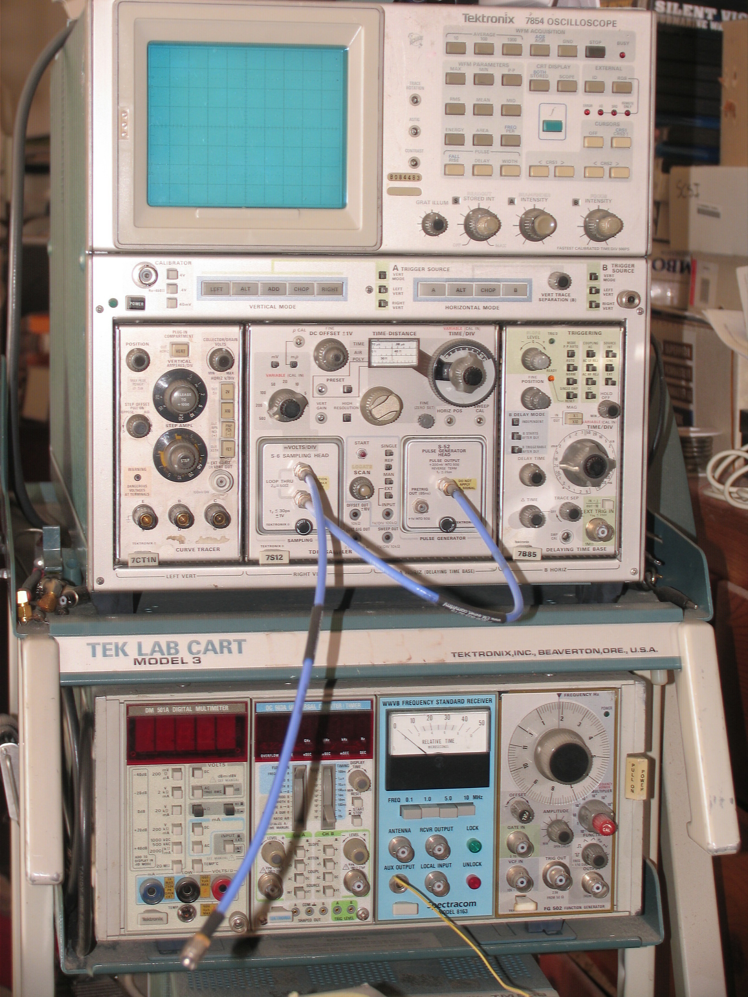
Electronic test equipment is used to create signals and capture responses from electronic devices under test (DUTs). In this way, the proper operation of the DUT can be proven or faults in the device can be traced. Use of electronic test equipment is essential to any serious work on electronics systems. Practical electronics engineering and assembly requires the use of many different kinds of electronic test equipment ranging from the very simple and inexpensive (such as a test light consisting of just a light bulb and a test lead) to extremely complex and sophisticated such as automatic test equipment (ATE). ATE often includes many of these instruments in real and simulated forms. Generally, more advanced test gear is necessary when developing circuits and systems than is needed when doing production testing or when troubleshooting existing production units in the field. Types of test equipment Basic equipment The following items are used for basic measurement of voltages, cur ... [...More Info...] [...Related Items...] OR: [Wikipedia] [Google] [Baidu] |


