|
Circle Diagram
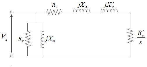
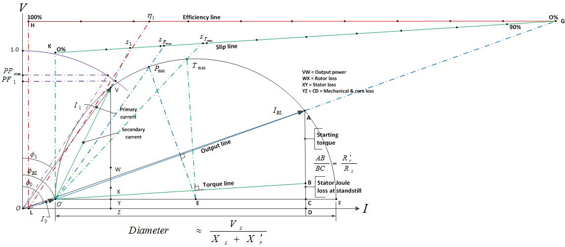
First conceived by A.heyland in 1894 and B.A. Behrend in 1895, the circle diagram is the graphical representation of the performance of the electrical machine drawn in terms of the locus of the machine's input voltage and current. The circle diagram can be drawn for alternators, synchronous motors, transformers, induction motors. The Heyland diagram is an approximate representation of circle diagram applied to induction motors, which assumes that stator input voltage, rotor resistance and rotor reactance are constant and stator resistance and core loss are zero. Another common circle diagram form is as described in the two constant air-gap induction motor images shown here, where, * Rs, Xs: Stator resistance and leakage reactance * Rr', Xr', s: Rotor resistance and leakage reactance referred to the stator and rotor slip * Rc, Xm, : Core and mechanical losses, magnetization reactance * Vs, Impressed stator voltage * I0 = OO', IBL = OA, I1 =OV: No load current, blocked rotor curren ... [...More Info...] [...Related Items...] OR: [Wikipedia] [Google] [Baidu] |
Electrical Machine
In electrical engineering, electric machine is a general term for machines using electromagnetic forces, such as electric motors, electric generators, and others. They are electromechanical energy converters: an electric motor converts electricity to mechanical power while an electric generator converts mechanical power to electricity. The moving parts in a machine can be rotating (''rotating machines'') or linear (''linear machines''). Besides motors and generators, a third category often included is transformers, which although they do not have any moving parts are also energy converters, changing the voltage level of an alternating current.Flanagan. Handbook of Transformer Design and Applications, Chap. 1 p1. Electric machines, in the form of generators, produce virtually all electric power on Earth, and in the form of electric motors consume approximately 60% of all electric power produced. Electric machines were developed beginning in the mid 19th century and since that time ... [...More Info...] [...Related Items...] OR: [Wikipedia] [Google] [Baidu] |
Alternator
An alternator is an electrical generator that converts mechanical energy to electrical energy in the form of alternating current. For reasons of cost and simplicity, most alternators use a rotating magnetic field with a stationary armature.Gordon R. Selmon, ''Magnetoelectric Devices'', John Wiley and Sons, 1966 no ISBN pp. 391-393 Occasionally, a linear alternator or a rotating armature with a stationary magnetic field is used. In principle, any AC electrical generator can be called an alternator, but usually the term refers to small rotating machines driven by automotive and other internal combustion engines. An alternator that uses a permanent magnet for its magnetic field is called a magneto. Alternators in power stations driven by steam turbines are called turbo-alternators. Large 50 or 60 Hz three-phase alternators in power plants generate most of the world's electric power, which is distributed by electric power grids. History Alternating current generating ... [...More Info...] [...Related Items...] OR: [Wikipedia] [Google] [Baidu] |
Synchronous Motor
A synchronous electric motor is an AC electric motor in which, at steady state, the rotation of the shaft is synchronized with the frequency of the supply current; the rotation period is exactly equal to an integral number of AC cycles. Synchronous motors contain multiphase AC electromagnets on the stator of the motor that create a magnetic field which rotates in time with the oscillations of the line current. The rotor with permanent magnets or electromagnets turns in step with the stator field at the same rate and as a result, provides the second synchronized rotating magnet field of any AC motor. A synchronous motor is termed ''doubly fed'' if it is supplied with independently excited multiphase AC electromagnets on both the rotor and stator. The synchronous motor and the induction motor are the most widely used types of AC motors. The difference between the two types is that the synchronous motor rotates at a rate locked to the line frequency since it does not rely on ... [...More Info...] [...Related Items...] OR: [Wikipedia] [Google] [Baidu] |
Transformer
A transformer is a passive component that transfers electrical energy from one electrical circuit to another circuit, or multiple circuits. A varying current in any coil of the transformer produces a varying magnetic flux in the transformer's core, which induces a varying electromotive force (EMF) across any other coils wound around the same core. Electrical energy can be transferred between separate coils without a metallic (conductive) connection between the two circuits. Faraday's law of induction, discovered in 1831, describes the induced voltage effect in any coil due to a changing magnetic flux encircled by the coil. Transformers are used to change AC voltage levels, such transformers being termed step-up or step-down type to increase or decrease voltage level, respectively. Transformers can also be used to provide galvanic isolation between circuits as well as to couple stages of signal-processing circuits. Since the invention of the first constant-potential transfo ... [...More Info...] [...Related Items...] OR: [Wikipedia] [Google] [Baidu] |
Induction Motor
An induction motor or asynchronous motor is an AC electric motor in which the electric current in the rotor needed to produce torque is obtained by electromagnetic induction from the magnetic field of the stator winding. An induction motor can therefore be made without electrical connections to the rotor. An induction motor's rotor can be either wound type or squirrel-cage type. Three-phase squirrel-cage induction motors are widely used as industrial drives because they are self-starting, reliable and economical. Single-phase induction motors are used extensively for smaller loads, such as household appliances like fans. Although traditionally used in fixed-speed service, induction motors are increasingly being used with variable-frequency drives (VFD) in variable-speed service. VFDs offer especially important energy savings opportunities for existing and prospective induction motors in variable-torque centrifugal fan, pump and compressor load applications. Squirrel ... [...More Info...] [...Related Items...] OR: [Wikipedia] [Google] [Baidu] |
Open-circuit Test
The open-circuit test, or no-load test, is one of the methods used in electrical engineering to determine the no-load impedance in the excitation branch of a transformer. The no load is represented by the open circuit, which is represented on the right side of the figure as the "hole" or incomplete part of the circuit. Method The secondary of the transformer is left open-circuited. A wattmeter is connected to the primary. An ammeter is connected in series with the primary winding. A voltmeter is optional since the applied voltage is the same as the voltmeter reading. Rated voltage is applied at primary. If the applied voltage is normal voltage then normal flux will be set up. Since iron loss is a function of applied voltage, normal iron loss will occur. Hence the iron loss is maximum at rated voltage. This maximum iron loss is measured using the wattmeter. Since the impedance of the series winding of the transformer is very small compared to that of the excitation branch, all o ... [...More Info...] [...Related Items...] OR: [Wikipedia] [Google] [Baidu] |
Short-circuit Test
The purpose of a short-circuit test is to determine the series branch parameters of the equivalent circuit of a transformer. Method The test is conducted on the high-voltage (HV) side of the transformer where the low-voltage (LV) side (or the secondary) is short-circuited. A wattmeter is connected to the primary side. An ammeter is connected in series with the primary winding. A voltmeter is optional since the applied voltage is the same as the voltmeter reading. Now with the help of a variac, the applied voltage is slowly increased until the ammeter gives a reading equal to the rated current of the HV side. After reaching the rated current of the HV side, all three instruments reading (Voltmeter, Ammeter, and wattmeter readings) are recorded. The ammeter reading gives the primary equivalent of full load current IL. As the voltage applied for full load current in short circuit test on transformer is quite small compared to the rated primary voltage of the transformer, the ir ... [...More Info...] [...Related Items...] OR: [Wikipedia] [Google] [Baidu] |
Blocked Rotor Test
A blocked rotor test is conducted on an induction motor. It is also known as short-circuit test (because it is mechanical–electrical analogies#Mobility analogies, the mechanical analogy of a transformer short-circuit test), locked rotor test or stalled torque test. From this test, short-circuit current at Voltage, normal voltage, power factor on short circuit, total Electrical reactance, leakage reactance, and Torque, starting torque of the motor can be found. It is very important to know a motor's starting torque since if it is not enough to overcome the initial friction of its intended load then it will remain stationary while drawing an excessive current and rapidly overheat. The test may be conducted at lower voltage because at the normal voltage the current through the windings would be high enough to rapidly overheat and damage them. The test may still be conducted at full voltage if it is brief enough to avoid overheating the windings or overloading the starting circuits, but ... [...More Info...] [...Related Items...] OR: [Wikipedia] [Google] [Baidu] |
Circle Diagram
First conceived by A.heyland in 1894 and B.A. Behrend in 1895, the circle diagram is the graphical representation of the performance of the electrical machine drawn in terms of the locus of the machine's input voltage and current. The circle diagram can be drawn for alternators, synchronous motors, transformers, induction motors. The Heyland diagram is an approximate representation of circle diagram applied to induction motors, which assumes that stator input voltage, rotor resistance and rotor reactance are constant and stator resistance and core loss are zero. Another common circle diagram form is as described in the two constant air-gap induction motor images shown here, where, * Rs, Xs: Stator resistance and leakage reactance * Rr', Xr', s: Rotor resistance and leakage reactance referred to the stator and rotor slip * Rc, Xm, : Core and mechanical losses, magnetization reactance * Vs, Impressed stator voltage * I0 = OO', IBL = OA, I1 =OV: No load current, blocked rotor curren ... [...More Info...] [...Related Items...] OR: [Wikipedia] [Google] [Baidu] |
Induction Motor
An induction motor or asynchronous motor is an AC electric motor in which the electric current in the rotor needed to produce torque is obtained by electromagnetic induction from the magnetic field of the stator winding. An induction motor can therefore be made without electrical connections to the rotor. An induction motor's rotor can be either wound type or squirrel-cage type. Three-phase squirrel-cage induction motors are widely used as industrial drives because they are self-starting, reliable and economical. Single-phase induction motors are used extensively for smaller loads, such as household appliances like fans. Although traditionally used in fixed-speed service, induction motors are increasingly being used with variable-frequency drives (VFD) in variable-speed service. VFDs offer especially important energy savings opportunities for existing and prospective induction motors in variable-torque centrifugal fan, pump and compressor load applications. Squirrel ... [...More Info...] [...Related Items...] OR: [Wikipedia] [Google] [Baidu] |
Electromechanical Engineering
In engineering, electromechanics combines processes and procedures drawn from electrical engineering and mechanical engineering. Electromechanics focuses on the interaction of electrical and mechanical systems as a whole and how the two systems interact with each other. This process is especially prominent in systems such as those of DC or AC rotating electrical machines which can be designed and operated to generate power from a mechanical process (generator) or used to power a mechanical effect (motor). Electrical engineering in this context also encompasses electronics engineering. Electromechanical devices are ones which have both electrical and mechanical processes. Strictly speaking, a manually operated switch is an electromechanical component due to the mechanical movement causing an electrical output. Though this is true, the term is usually understood to refer to devices which involve an electrical signal to create mechanical movement, or vice versa mechanical movement ... [...More Info...] [...Related Items...] OR: [Wikipedia] [Google] [Baidu] |


