|
Binary Cutter Location
A cutter location (CLData) refers to the position which a CNC milling machine has been instructed to hold a milling cutter by the instructions in the program (typically G-code). Each line of motion controlling G-code consists of two parts: the type of motion from the last cutter location to the next cutter location (e.g. "G01" means linear, "G02" means circular), and the next cutter location itself (the cartesian point (20, 1.3, 4.409) in this example). "G01 X20Y1.3Z4.409" The fundamental basis for creating the cutter paths suitable for CNC milling are functions that can find valid cutter locations, and stringing them together in a series. There are two broad and conflicting approaches to the problem of generating valid cutter locations, given a CAD model and a tool definition: calculation by offsets, and calculation against triangles. Each is discussed in a later section of this article. The most common example of the general cutter location problem is cutter radius compensat ... [...More Info...] [...Related Items...] OR: [Wikipedia] [Google] [Baidu] [Amazon] |
Milling Machine
Milling is the process of machining using rotary cutters to remove material by advancing a cutter into a workpiece. This may be done by varying directions on one or several axes, cutter head speed, and pressure. Milling covers a wide variety of different operations and machines, on scales from small individual parts to large, heavy-duty gang milling operations. It is one of the most commonly used processes for machining custom parts to precise tolerances. Milling can be done with a wide range of machine tools. The original class of machine tools for milling was the milling machine (often called a mill). After the advent of computer numerical control (CNC) in the 1960s, milling machines evolved into ''machining centers'': milling machines augmented by automatic tool changers, tool magazines or carousels, CNC capability, coolant systems, and enclosures. Milling centers are generally classified as vertical machining centers (VMCs) or horizontal machining centers (HMCs). The integr ... [...More Info...] [...Related Items...] OR: [Wikipedia] [Google] [Baidu] [Amazon] |
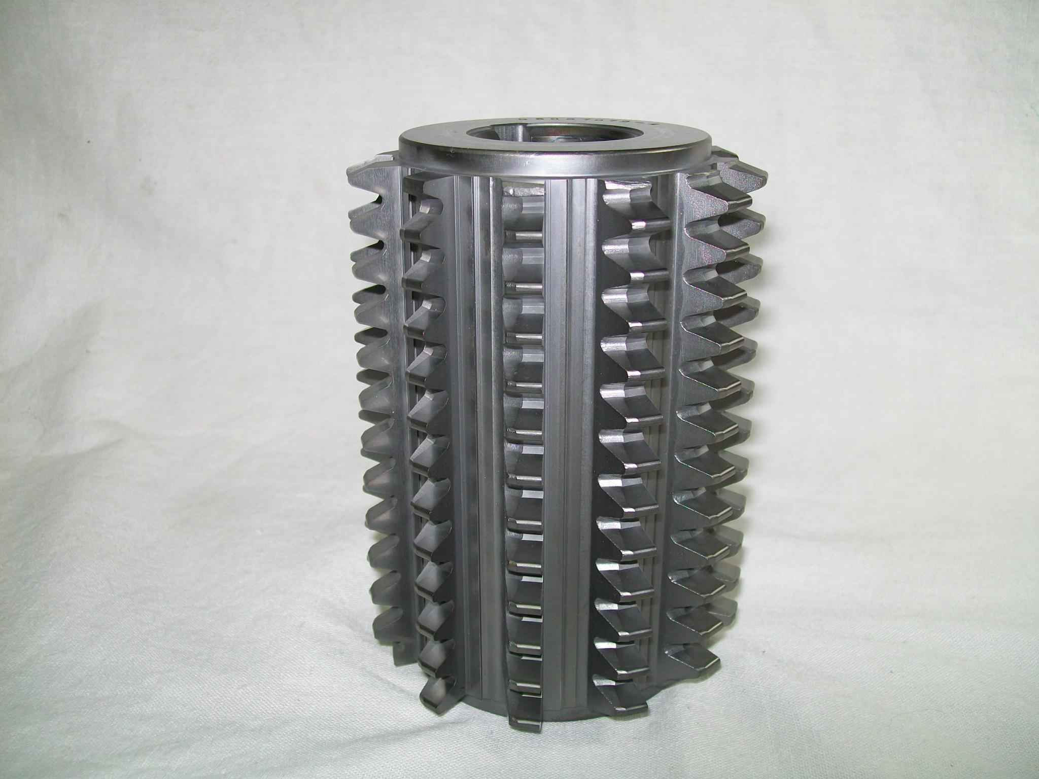
Milling Cutter
Milling cutters are cutting tools typically used in milling machines or machining centres to perform milling operations (and occasionally in other machine tools). They remove material by their movement within the machine (e.g., a ball nose mill) or directly from the cutter's shape (e.g., a form tool such as a hobbing cutter). Features Milling cutters come in several shapes and many sizes. There is also a choice of coatings, as well as rake angle and number of cutting surfaces. * Shape: Several standard shapes of milling cutters are used in industry today, which are explained in more detail below. * Flutes / teeth: The flutes of the milling bit are the deep helical grooves running up the cutter, while the sharp blade along the edge of the flute is known as the tooth. The tooth cuts the material, and chips of this material are pulled up the flute by the rotation of the cutter. There is almost always one tooth per flute, but some cutters have two teeth per flute. [...More Info...] [...Related Items...] OR: [Wikipedia] [Google] [Baidu] [Amazon] |
G-code
G-code (abbreviation for geometric code; also called RS-274, standardized today in ISO 6983-1) is the most widely used computer numerical control (CNC) and 3D printing programming language. It is used mainly in computer-aided manufacturing to control automated machine tools, as well as for 3D-printer slicer applications. G-code has many variants. G-code instructions are provided to a machine controller (industrial computer) that tells the motors where to move, how fast to move, and what path to follow. The two most common situations are that, within a machine tool such as a lathe or mill, a cutting tool is moved according to these instructions through a toolpath cutting away material to leave only the finished workpiece and/or an unfinished workpiece is precisely positioned in any of up to nine axes around the three dimensions relative to a toolpath and, either or both can move relative to each other. The same concept also extends to noncutting tools such as forming or b ... [...More Info...] [...Related Items...] OR: [Wikipedia] [Google] [Baidu] [Amazon] |
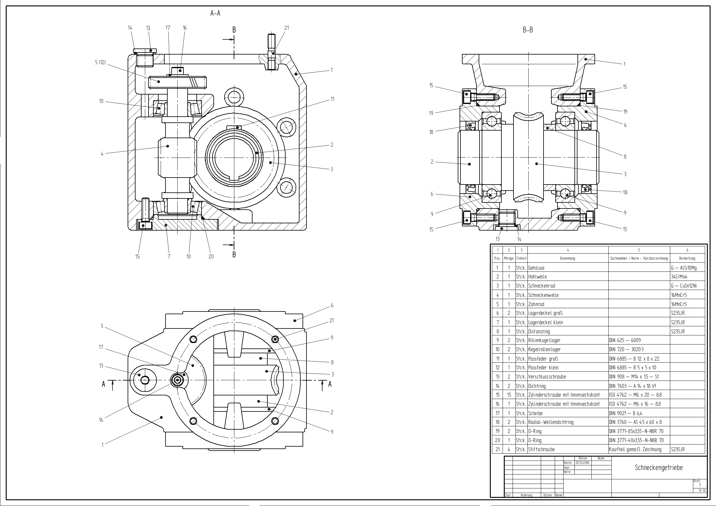
Computer-aided Design
Computer-aided design (CAD) is the use of computers (or ) to aid in the creation, modification, analysis, or optimization of a design. This software is used to increase the productivity of the designer, improve the quality of design, improve communications through documentation, and to create a database for manufacturing. Designs made through CAD software help protect products and inventions when used in patent applications. CAD output is often in the form of electronic files for print, machining, or other manufacturing operations. The terms computer-aided drafting (CAD) and computer-aided design and drafting (CADD) are also used. Its use in designing electronic systems is known as ''electronic design automation'' (''EDA''). In mechanical design it is known as ''mechanical design automation'' (''MDA''), which includes the process of creating a technical drawing with the use of computer software. CAD software for mechanical design uses either vector-based graphics to depict t ... [...More Info...] [...Related Items...] OR: [Wikipedia] [Google] [Baidu] [Amazon] |
Endmill
An end mill is a type of milling cutter, a cutting tool used in industrial milling applications. They can have several end configurations: round (ball), tapered, or straight are a few popular types. They are most commonly used in "milling machines" that move a piece of material against the end mill to remove chips of the material to create a desired size or shape. It is distinguished from the drill bit in its application, geometry, and manufacture. While a drill bit can only cut in the axial direction, most milling bits can cut in the radial direction. Not all mills can cut tangentially: those designed to do so are known as end mills. End mills are used in milling applications such as profile milling, tracer milling, face milling, and plunging. Types Several broad categories of end- and face-milling tools exist, such as center-cutting versus non-center-cutting (whether the mill can take plunging cuts); and categorization by number of flutes; by helix angle; by material; and b ... [...More Info...] [...Related Items...] OR: [Wikipedia] [Google] [Baidu] [Amazon] |
Computer-aided Manufacturing
Computer-aided manufacturing (CAM) also known as computer-aided modeling or computer-aided machining is the use of software to control machine tools in the manufacturing of work pieces. This is not the only definition for CAM, but it is the most common. It may also refer to the use of a computer to assist in all operations of a manufacturing plant, including planning, Industrial management, management, transportation and storage. Its primary purpose is to create a faster production process and components and tooling with more precise dimensions and material consistency, which in some cases, uses only the required amount of raw material (thus minimizing waste), while simultaneously reducing energy consumption. CAM is now a system used in schools and lower educational purposes. CAM is a subsequent computer-aided process after computer-aided design (CAD) and sometimes computer-aided engineering (CAE), as the model generated in CAD and verified in CAE can be input into CAM software, w ... [...More Info...] [...Related Items...] OR: [Wikipedia] [Google] [Baidu] [Amazon] |
Freeform Surface
Freeform surface modelling is a technique for engineering freeform surfaces with a CAD or CAID system. The technology has encompassed two main fields. Either creating aesthetic surfaces ( class A surfaces) that also perform a function; for example, car bodies and consumer product outer forms, or technical surfaces for components such as gas turbine blades and other fluid dynamic engineering components. CAD software packages use two basic methods for the creation of surfaces. The first begins with construction curves ( splines) from which the 3D surface is then swept (section along guide rail) or meshed (lofted) through. The second method is direct creation of the surface with manipulation of the surface poles/control points. From these initially created surfaces, other surfaces are constructed using either derived methods such as offset or angled extensions from surfaces; or via bridging and blending between groups of surfaces. Surfaces Freeform surface, or freeform ... [...More Info...] [...Related Items...] OR: [Wikipedia] [Google] [Baidu] [Amazon] |
Kd-tree
In computer science, a ''k''-d tree (short for ''k-dimensional tree'') is a space-partitioning data structure for organizing points in a ''k''-dimensional space. K-dimensional is that which concerns exactly k orthogonal axes or a space of any number of dimensions. ''k''-d trees are a useful data structure for several applications, such as: * Searches involving a multidimensional search key (e.g. range searches and nearest neighbor searches) & * Creating point clouds. ''k''-d trees are a special case of binary space partitioning trees. Description The ''k''-d tree is a binary tree in which ''every'' node is a ''k''-dimensional point. Every non-leaf node can be thought of as implicitly generating a splitting hyperplane that divides the space into two parts, known as half-spaces. Points to the left of this hyperplane are represented by the left subtree of that node and points to the right of the hyperplane are represented by the right subtree. The hyperplane direction is ... [...More Info...] [...Related Items...] OR: [Wikipedia] [Google] [Baidu] [Amazon] |
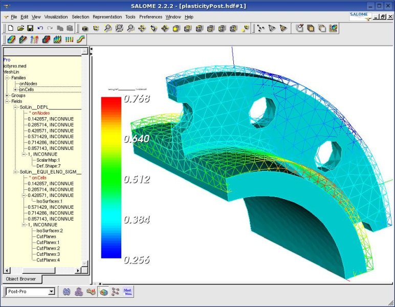
Computer-aided Engineering
Computer-aided engineering (CAE) is the general usage of technology to aid in tasks related to engineering analysis. Any use of technology to solve or assist engineering issues falls under this umbrella. Overview Following alongside the consistent improvement in computer graphics and speed, computer aid assists engineers with once complicated and time consuming tasks with the input of information and a press of a button. It includes finite element method or analysis (FEA), computational fluid dynamics (CFD), multibody dynamics (MBD), durability and optimization. It is included with computer-aided design (CAD) and computer-aided manufacturing (CAM) in a collective term and abbreviation computer-aided technologies (CAx). The term CAE has been used to describe the use of computer technology within engineering in a broader sense than just engineering analysis. It was in this context that the term was coined by Jason Lemon, founder of Structural Dynamics Research Corporation ( ... [...More Info...] [...Related Items...] OR: [Wikipedia] [Google] [Baidu] [Amazon] |


