|
Boost Controller
In turbocharged internal combustion engines, a boost controller is a device sometimes used to increase the boost pressure produced by the turbocharger. It achieves this by reducing the boost pressure seen by the wastegate. Operation The purpose of a boost controller is to reduce the boost pressure seen by the wastegate's reference port, in order to trick the wastegate into allowing higher boost pressures than it was designed for. Many boost controllers use a needle valve that is opened and closed by an electric solenoid. By varying the pulse width to the solenoid, the solenoid valve can be commanded to be open a certain percentage of the time. This effectively alters the flow rate of air pressure through the valve, changing the amount of air that is bled out instead of going to the wastegate's reference port. Solenoids may require small diameter restrictors be installed in the air control lines to limit airflow and even out the on/off nature of their operation. Two-port solenoi ... [...More Info...] [...Related Items...] OR: [Wikipedia] [Google] [Baidu] |
Turbocharger
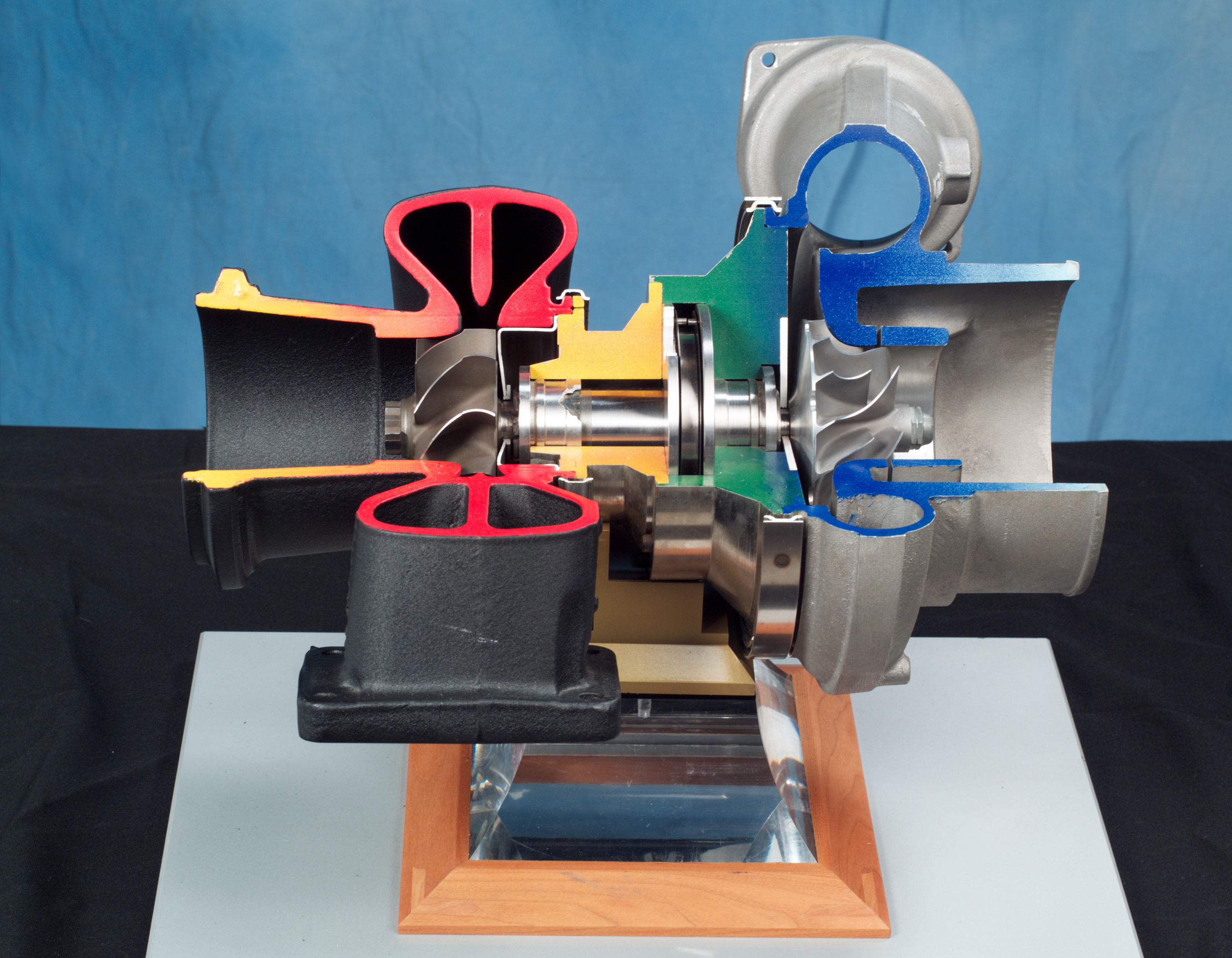
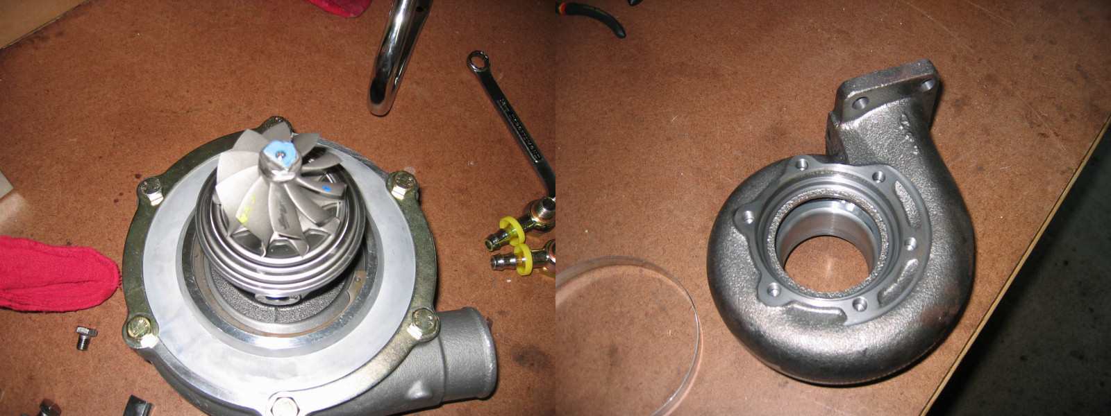
In an internal combustion engine, a turbocharger (often called a turbo) is a forced induction device that is powered by the flow of exhaust gases. It uses this energy to compress the intake gas, forcing more air into the engine in order to produce more power for a given displacement. The current categorisation is that a turbocharger is powered by the kinetic energy of the exhaust gasses, whereas a supercharger is mechanically powered (usually by a belt from the engine's crankshaft). However, up until the mid-20th century, a turbocharger was called a "turbosupercharger" and was considered a type of supercharger. History Prior to the invention of the turbocharger, |
Variable Geometry Turbocharger
Variable-geometry turbochargers (VGTs), occasionally known as variable-nozzle turbines (VNTs), are a type of turbochargers, usually designed to allow the effective aspect ratio of the turbocharger to be altered as conditions change. This is done with the use of adjustable vanes located inside the turbine housing between the inlet and turbine, these vanes affect flow of gases towards the turbine. The benefit of the VGT is that the optimum aspect ratio at low engine speeds is very different from that at high engine speeds. If the aspect ratio is too large, the turbo will fail to create boost at low speeds; if the aspect ratio is too small, the turbo will choke the engine at high speeds, leading to high exhaust manifold pressures, high pumping losses, and ultimately lower power output. By altering the geometry of the turbine housing as the engine accelerates, the turbo's aspect ratio can be maintained at its optimum. Because of this, VGTs have a minimal amount of lag, a low boost th ... [...More Info...] [...Related Items...] OR: [Wikipedia] [Google] [Baidu] |
Blowoff Valve
A blowoff valve (also called dump valve or compressor bypass valve) is a pressure release system present in most petrol turbocharger, turbocharged engines. Blowoff valves are used to reduce pressure in the intake system as the throttle is closed, thus preventing Compressor stall, compressor surge. Design A key function of blowoff valves is to prevent Compressor stall, compressor surge, a phenomenon that would otherwise occur as the throttle is closed in a turbocharged engine. If the turbocharger's compressor wheel is spinning at high speed when the throttle is suddenly closed (such as during a gear change), the flow reduces beyond the surge line of the compressor. At this point the change in pressure across the compressor reduces, leading to a collapse in flow and possibly even flow reversal and a collapse in plenum pressure. As the compressor is still spinning at high speed, once the flow has reduced sufficiently, the change in pressure across the compressor begins to rise an ... [...More Info...] [...Related Items...] OR: [Wikipedia] [Google] [Baidu] |
Butterfly Valve
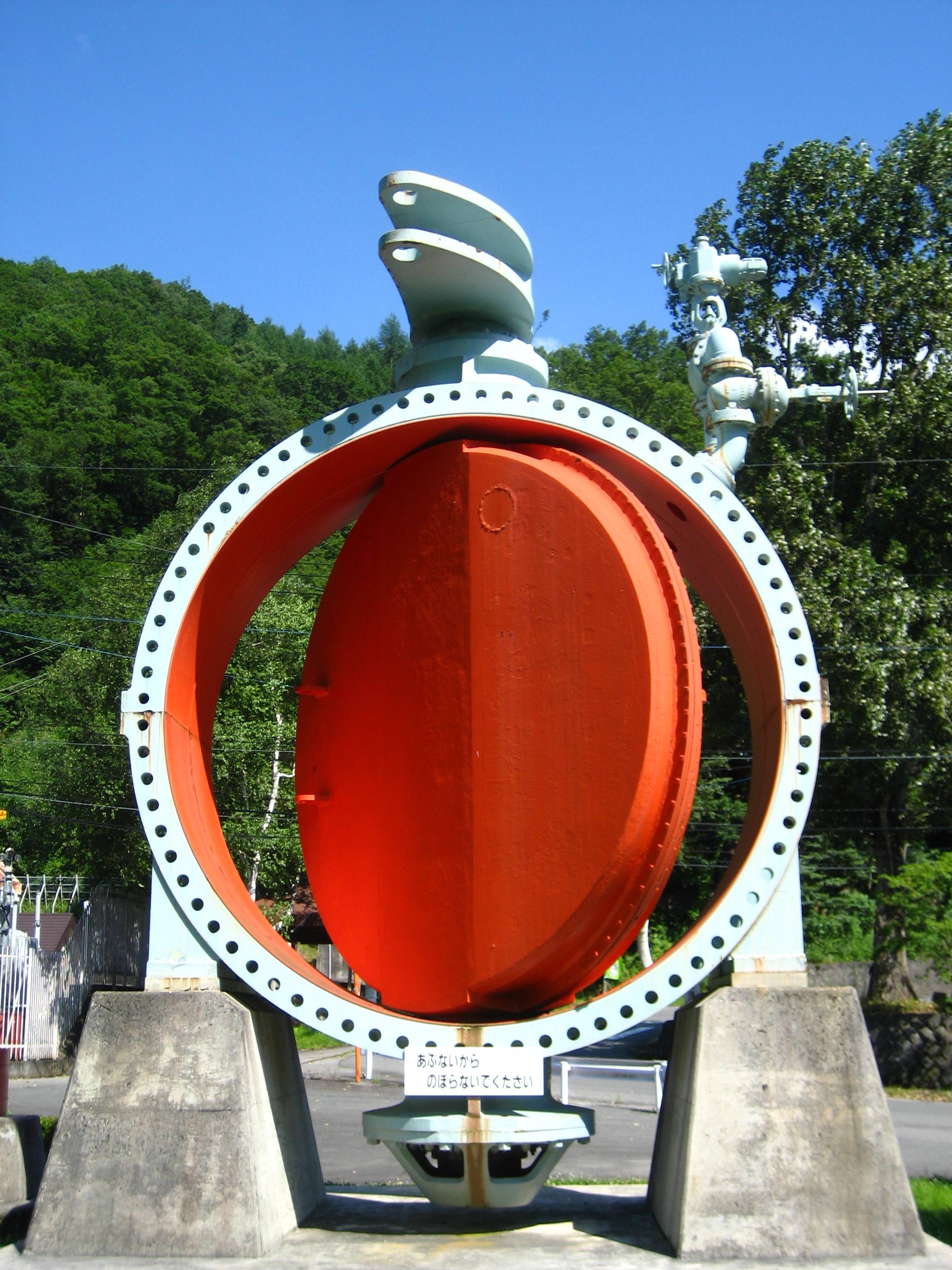
A butterfly valve is a valve that isolates or regulates the flow of a fluid. The closing mechanism is a disk that rotates. Principle of operation Operation is similar to that of a ball valve, which allows for quick shut off. Butterfly valves are generally favored because they cost less than other valve designs, and are lighter weight so they need less support. The disc is positioned in the center of the pipe. A rod passes through the disc to an actuator on the outside of the valve. Rotating the actuator turns the disc either parallel or perpendicular to the flow. Unlike a ball valve, the disc is always present within the flow, so it induces a pressure drop, even when open. A butterfly valve is from a family of valves called quarter-turn valves. In operation, the valve is fully open or closed when the disc is rotated a quarter turn. The "butterfly" is a metal disc mounted on a rod. When the valve is closed, the disc is turned so that it completely blocks off the passageway. Wh ... [...More Info...] [...Related Items...] OR: [Wikipedia] [Google] [Baidu] |
Intake Manifold
In automotive engineering, an inlet manifold or intake manifold (in American English) is the part of an engine that supplies the fuel/air mixture to the cylinders. The word ''manifold'' comes from the Old English word ''manigfeald'' (from the Anglo-Saxon ''manig'' anyand ''feald'' epeatedly and refers to the multiplying of one (pipe) into many.manifold, (adv.) "in the proportion of many to one, by many times". AD1526 ''Oxford English Dictionary'', In contrast, an exhaust manifold collects the exhaust gases from multiple cylinders into a smaller number of pipes – often down to one pipe. The primary function of the intake manifold is to ''evenly'' distribute the combustion mixture (or just air in a direct injection engine) to each intake port in the cylinder head(s). Even distribution is important to optimize the efficiency and performance of the engine. It may also serve as a mount for the carburetor, throttle body, fuel injectors and other components of the engine ... [...More Info...] [...Related Items...] OR: [Wikipedia] [Google] [Baidu] |
Failure Mode
Failure causes are defects in design, process, quality, or part application, which are the underlying cause of a failure or which initiate a process which leads to failure. Where failure depends on the user of the product or process, then human error must be considered. Component failure / failure modes A part failure mode is the way in which a component failed "functionally" on the component level. Often a part has only a few failure modes. For example, a relay may fail to open or close contacts on demand. The failure mechanism that caused this can be of many different kinds, and often multiple factors play a role at the same time. They include corrosion, welding of contacts due to an abnormal electric current, return spring fatigue failure, unintended command failure, dust accumulation and blockage of mechanism, etc. Seldom only one cause (hazard) can be identified that creates system failures. The real root causes can in theory in most cases be traced back to some kind of huma ... [...More Info...] [...Related Items...] OR: [Wikipedia] [Google] [Baidu] |
Backpressure
Back pressure (or backpressure) is a resistance or force opposing the desired flow of fluid through pipes, leading to friction loss and pressure drop. The term ''back pressure'' is a misnomer, as pressure is a scalar quantity, so it has a magnitude but no direction. The fluid is what is directed, tending to flow away from high-pressure regions and toward low-pressure regions. If the low-pressure space is more high-pressure than intended (e.g. due to obstructions or tight bends in an exhaust pipe) or the high-pressure space is more low-pressure than intended, this opposes the desired flow and reduces the discharge. Similarly, bending or other operations on a pipe (such as a stock car exhaust system with a particularly high number of twists and bends) can reduce flow rate. Explanation A common example of backpressure is that caused by the exhaust system (consisting of the exhaust manifold, catalytic converter, muffler and connecting pipes) of an automotive four-stroke engine, wh ... [...More Info...] [...Related Items...] OR: [Wikipedia] [Google] [Baidu] |
Boost (automotive Engineering)
In an internal combustion engine, a turbocharger (often called a turbo) is a forced induction device that is powered by the flow of exhaust gases. It uses this energy to compress the intake gas, forcing more air into the engine in order to produce more power for a given displacement. The current categorisation is that a turbocharger is powered by the kinetic energy of the exhaust gasses, whereas a supercharger is mechanically powered (usually by a belt from the engine's crankshaft). However, up until the mid-20th century, a turbocharger was called a "turbosupercharger" and was considered a type of supercharger. History Prior to the invention of the turbocharger, |
Manifold Absolute Pressure Sensor
The manifold absolute pressure sensor (MAP sensor) is one of the sensors used in an internal combustion engine's electronic control system. Engines that use a MAP sensor are typically fuel injected. The manifold absolute pressure sensor provides instantaneous manifold pressure information to the engine's electronic control unit (ECU). The data is used to calculate air density and determine the engine's air mass flow rate, which in turn determines the required fuel metering for optimum combustion (see stoichiometry) and influence the advance or retard of ignition timing. A fuel-injected engine may alternatively use a mass airflow sensor (MAF sensor) to detect the intake airflow. A typical naturally aspirated engine configuration employs one or the other, whereas forced induction engines typically use both; a MAF sensor on the Cold Air Intake leading to the turbo and a MAP sensor on the intake tract post-turbo before the throttle body on the intake manifold. MAP sensor data can ... [...More Info...] [...Related Items...] OR: [Wikipedia] [Google] [Baidu] |
Feedback Loop
Feedback occurs when outputs of a system are routed back as inputs as part of a chain of cause-and-effect that forms a circuit or loop. The system can then be said to ''feed back'' into itself. The notion of cause-and-effect has to be handled carefully when applied to feedback systems: History Self-regulating mechanisms have existed since antiquity, and the idea of feedback had started to enter economic theory in Britain by the 18th century, but it was not at that time recognized as a universal abstraction and so did not have a name. The first ever known artificial feedback device was a float valve, for maintaining water at a constant level, invented in 270 BC in Alexandria, Egypt. This device illustrated the principle of feedback: a low water level opens the valve, the rising water then provides feedback into the system, closing the valve when the required level is reached. This then reoccurs in a circular fashion as the water level fluctuates. Centrifugal governors were u ... [...More Info...] [...Related Items...] OR: [Wikipedia] [Google] [Baidu] |
Revolutions Per Minute
Revolutions per minute (abbreviated rpm, RPM, rev/min, r/min, or with the notation min−1) is a unit of rotational speed or rotational frequency for rotating machines. Standards ISO 80000-3:2019 defines a unit of rotation as the dimensionless unit equal to 1, which it refers to as a revolution, but does not define the revolution as a unit. It defines a unit of rotational frequency equal to s−1. The superseded standard ISO 80000-3:2006 did however state with reference to the unit name 'one', symbol '1', that "The special name revolution, symbol r, for this unit is widely used in specifications on rotating machines." The International System of Units (SI) does not recognize rpm as a unit, and defines the unit of frequency, Hz, as equal to s−1. :\begin 1~&\text &&=& 60~&\text \\ \frac~&\text &&=& 1~&\text \end A corresponding but distinct quantity for describing rotation is angular velocity, for which the SI unit is the ra ... [...More Info...] [...Related Items...] OR: [Wikipedia] [Google] [Baidu] |


